|
|
I've always been interested in the stars, but South West London, which is where I lived until recently, with its light pollution was a less-than-ideal place to indulge. Having said that, I nonetheless did get myself Now I live in South West Cork, Ireland, which is very dark, (Bortle 3 evidently) and obviously all the more worthwhile: i.e. very dark skies. Messier 44, the Beehive Cluster, is naked-eye visible, as are the Great Hercules Cluster (M13) and the Andromeda Galaxy (M31). The Milky Way is strikingly obvious. Where we were 20 miles SW of London, it was (still is) Bortle 7, and none of those objects were even remotely visible naked eye. As of Feb 2022, expect before too long an article on light pollution: modelled, measured and compared between those two places. Further articles will cover Newtonian Collimation; my rather extended scope collection; |
||||||||||||||||||||||||||||||||||||
|
Our Solar System, the Planets and When and How Best to See Them (updated May 2023)
Our Solar System comprises 8 official Planets and Pluto (not to mention 556,000-ish comets, asteroids and other Moons). In order of distance of their orbits from the Sun, these 9 are Mercury, Venus, Earth, Mars, Jupiter, Saturn, Uranus, Neptune,
In common with the Moon, most of the Planets provide interesting viewing for amateur astronomers even from places of bad light pollution. However, unlike most celestial objects, they do not appear in the same places in the sky at the same times of year. The word Planet derives from the Greek Planetes, which means 'wanderer'. The following paragraphs and charts are guides as to the best times for the near future to observe them. Excepting Mercury and Venus, the charts plot each planet's altitude, in degrees, 2 hours after sunset by which time it should be astronomically dark. Mercury needs different treatment because it's always so close to the Sun. Venus because it's almost too bright, magnitude -4, to view when completely dark. Thus Mercury's charts show its altitude when the Sun is 3 degrees below the horizon, which is roughly when it should start to become visible to the naked eye. Venus' chart shows its altitude when the Sun is at 6 degrees down, the transition between civil twilight and nautical twilight.. Mercury (updated May 2023) Mercury is the closest planet to the Sun, the distance of its orbit from the Sun varying between 31% and 47% of Earth’s, meaning its maximum apparent distance from the Sun is never more than about 23 degrees of arc across the sky (about the distance between your outstretched little-finger tip and thumb-tip at arm's length) and mostly much less. Because the immediate “movement” of the Sun during the day (and that of any other Celestial object including the Planets) is overwhelmingly due to the Earth’s rotation, not the object’s own movement, Mercury is basically following (or preceding) the Sun down, and there is never much time between Sun-set and "Mercury-set". Luckily, when fully illuminated, its brightness approaches that of the brightest star in the sky, at around magnitude -1. Sirius, the brightest star, has magnitude -1.46. Even at 50% illumination, "D"-shaped, a half- Consequently, the only realistic time to see Mercury is shortly after the Sun has set during twilight, and when it’s at “maximum elongation”, i.e. thrown out as far sideways in its orbit around the Sun from the viewpoint of an earthly observer. Furthermore, when it is at maximum elongation, the geometry of the situation means that it’ll be approximately 50% illuminated, and waning (getting less). The charts below show, for now and the near future, the altitude of Mercury each day when the Sun is 3 degrees below the horizon. They also show, in light blue on a scale from 0 to 1 (0% to 100%) the phase of Mercury, i.e. how much of a crescent or "full disc" it appears. Even seasoned astronomers get excited about seeing Mercury.
For an observer at 51 degrees N (e.g. London):
One year's pattern roughly repeats itself from a current year to the next, with the relevant events happening around a fortnight earlier each year.
For an observer at 33 degrees S (Sydney or Capetown):
Similarly to the Northern Hemisphere, the pattern more or less repeats every year. Venus (updated May 2023) Like Mercury, Venus’ orbit is inside that of Earth. Which means that it too follows the Sun down at Sunset when it’s that side of its orbit, and precedes the Sun at Sunrise when it’s on the other side of the Sun. Thus, being the first “star” to be visible as twilight beckons on account of its extreme brightness, Venus is often known as the Evening Star or the Morning Star. In fact it’s so extremely bright, magnitude -4 and therefore easily the brightest non-Sun object in the sky when it’s up, that it’s perfectly visible during the day as well. I actually prefer to view it in daytime because only then is it not dazzling in a telescope, and it's a nice party trick for the non-initiated. You likely won’t have noticed it during the day as it’s a tiny bright speck in an otherwise bright blue sky. To see it through binoculars, you do need to “hunt around” in the right area until you see the bright dot. Ironically, with a telescope it’s easier. Use an App to find the approximate altitude of Venus for the moment, and using a digital inclinometer, set the angle of the telescope to that angle. Then point the scope in roughly the right direction and scan from side to side. You’ll find it quickly. Observing Venus in darkness can be frustrating, because if there’s even a little turbulence in the atmosphere, called “bad seeing”, it will twinkle to the naked eye and the view through a telescope will produce enough sparkle and glare that you can’t really make out its shape. Venus 2023-2024
Northern Hemisphere
Southern Hemisphere
In support, the charts of Venus’ altitude I present below are of Venus just after sunset, viewed from the Northern latitudes, London, and from Southern latitudes, e.g. Sydney or Capetown. Mars (updated May 2023) Mercury’s and Venus’ orbit sit inside Earth’s orbit, meaning from an Earthly observer's point of view, Mercury and Venus appear to “follow the Sun around”, either ahead or behind. Consequently Mercury offers few opportunities for observing, and Venus is known as the Evening Star or Morning Star, depending on which side of the Sun it is. Mars is different. His orbit, the outermost of the 4 “rocky” planets, sits outside Earth’s orbit. This means that Mars’ distance from and apparent size from an Earthly observer varies enormously, from as little as 4 arc-seconds (1 arcsec=1/3600 of a degree), when Mars and Earth are at opposite sides of the Sun, to more than five times bigger at over 22 arc-seconds when they’re both at the same points on their orbits and closest together.
LEFT: Closest Together (Opposition) ............. RIGHT: Far Apart
Because Earth orbits inside Mars, it necessarily orbits faster (Kepler’s 3rd Law), in fact about twice as fast. So the two planets get back to approximately their same relative positions about every two years. Thus a chart of Mars’ altitude (to an Earth-bound observer) will show a roughly two-year periodic pattern. Put another way, if Mars is at its closest (and biggest - called "Opposition") say now, one year later it will be at its furthest away, and vice versa. Mars 2023-2024 Mars from mid latitudes either North or South Hemisphere will be similar during 2023-2024. He’s visible reasonably high up from early 2023 until the Summer wherever you are, but unfortunately heading away from us and well past his peak size. So a rather small target in a telescope, making detail rather difficult to see. Better from the Southern Hemisphere though, from an elevation point of view.
Northern Hemisphere
Jupiter (updated May 2023) Hop over the Asteroid Belt from Mars, and we get to the first of our two Gas Giants and our largest and most massive planet, Jupiter. Jupiter is very bright, second only to Venus amongst the planets. Jupiter orbits 5 times further from the Sun than earth, taking 12 years to complete an orbit. Along with Saturn, it’s truly the most spectacular planet to observe through a telescope, and is a real test of a scope’s quality. On a night of good “seeing” and with a scope of high quality, its bands and details within its bands are discernible, as well as the Great Red Spot. Its 4 largest Moons, the so-called “Galilean Moons”, Io, Europa, Ganymede and Callisto, can usually be seen as a line of bright dots near the planet even through decent hand-held binoculars. Jupiter 2023-2024 Because Jupiter takes around 12 years to orbit the Sun, it will appear approximately 36 degrees further East at the same date each year. Its apparent altitude also changes each year, and at the time of writing (May 2023) Jupiter won’t re-appear for dark evenings until around November 2023. In the Northern Hemisphere, Jupiter has been slowly improving “maximum altitude” year by year, at a rate of nearly 14 degrees higher per year. Next Jupiter season, Nov 23 – Mar 24, he will reach over 50 degrees up, the best for years! It’s going to be fantastic. Not unlike Venus, Jupiter is often best viewed during twilight. Its disc reveals a wealth of detail, several bands, whorls, and barges within the bands, depending on the night’s seeing and the quality of your scope. A lot of Jupiter’s detail can be seen in colour, so ironically its detail is actually best seen in twilight, when your Cones are still active (mesopic vision). Cones are your eyes’ colour cells, and they not only see colour, but are also more densely packed, so you see more detail too. By the time it’s truly dark, only your Rods are working, in monochrome (grey) and at less resolution (scotopic vision). The Southern Hemisphere will be broadly similar, though peaking a couple of months earlier, though reaching not quite as high as the NH at max elevation – a reversal of recent years.
Northern Hemisphere
Saturn (updated May 2023) Next out from Jupiter orbits Saturn. Although Saturn’s orbit is just under twice Jupiter’s distance from the Sun, it takes almost 3 times as long to complete an orbit: nearly 30 years in fact. Saturn is truly the Wow! Planet, that word invariably elicited when people see Saturn through a telescope for the very first time. They never forget that first look, and most never lose the sense of wonder every time they see it. I certainly don’t. Saturn has (as of May 2023) over 80 Moons of which several are visible in “backyard telescopes”. Its rings comprise almost entirely chunks of water ice, and the ring system is only about 20 metres (60 feet) thick! With a good telescope and good seeing, detail within Saturn’s rings can be seen, especially the so-called Cassini Division. Probably the same remarks about mesopic vision for Jupiter, see above, also apply to Saturn. Saturn 2023-2024 The “observing pattern” of Saturn lately has been similar to Jupiter, as they have been quite close together in the sky, and they both move relatively slowly across the stellar backdrop. Indeed Saturn and Jupiter exhibited a “Great Conjunction” in 2020, where they were nearly on top of one another! That was a sight to behold and won’t happen again until 2038. So good times for observing Saturn are not dissimilar to those for Jupiter, and indeed, like Jupiter, Saturn’s altitude from a NH observer is getting better year on year at the moment, just over 3.5 degrees higher at max per year. Its elevation is going to continue to improve for we NH-ers for at least a decade yet. Through a telescope, many of Saturn’s Moons are visible, though dimmer than those of Jupiter. So for the NH, Autumn-Winter will be Saturn season, rising to 25 degrees by Christmas and disappearing in the evenings by mid January. For SH-ers, Saturn’s pattern is similar, but peaks higher and for a slightly shorter time over the same months, i.e. during the SH Spring.
Northern Hemisphere
Uranus (updated May 2023) Uranus is the inner of the two “Ice Giants” (Jupiter and Saturn are the “Gas Giants”). Uranus is an oddity in some ways. The rest of the Solar System all mostly rotate and orbit in the same sense. If you were to look down from a long way above the solar system, you would see that all the planets orbit in more or less the same plane around the Sun, called The Ecliptic, they all orbit the Sun in the same direction and they nearly all rotate in that same direction. Which means their polar axes all point “up”, perpendicular-ish to the ecliptic and their orbits. However Uranus is an exception. Uranus has been “tipped over”, so its rotational axis is on its side. Which makes for very odd sunrises and sunsets! (Venus is also an oddity – it orbits like the rest, but rotates about its axis the other way). Uranus orbits nearly twenty times further from the Sun than Earth, and takes 84 years to complete an orbit. It starts to give human lifespan some perspective. For observers, Uranus is just beyond naked eye for all but the very darkest skies and the sharpest eyes. Through a scope, however, it’s easily found, clearly blue-greenish and clearly a disc not a star. Uranus 2023-2024 From NH skies, Uranus will only start to become observable again after November 2023, and will rapidly rise to 55 degrees elevation by early 2024. For SH observers, the pattern is similar, except peaking slightly earlier and lower.
Northern Hemisphere
Neptune (updated May 2023) Neptune is the outer of the two “Ice Giants”, orbiting 30 times as far as the earth and taking 165 years to complete an orbit around the Sun. To observe through a telescope, it’s a bit more of a challenge than Uranus, though under the right conditions it does appear greenish and as a disc, but you need high magnification to discern the latter. An experienced observer will certainly be able to find it. Neptune 2023-2024 From either hemisphere, Neptune becomes realistically visible from Sep 2024 until end-Jan 2024, reaching some 20 degrees higher in the SH than the NH.
Northern Hemisphere
|
||||||||||||||||||||||||||||||||||||
|
Reverse Engineering the Skywatcher Skymax180
Edit (Oct 2020): certain sections you�ll notice have been What follows should be of interest to anyone who wants to know any of the following 3 things about this, in my opinion rather nice, all things considered, scope: 1. What it looks like inside, its design, how it works, and how to dismantle it and re-assemble it safely (yes I�ve seen that video of someone disastrously taking apart a Skymax 150!). 2. Its real dimensions, including all the major components of the scope including internal mirror separation/s; 3. Its �key numbers� such as effective focal length for various amounts of back-focus or mirror separation, to allow more confident estimation of magnification, fields of view, exit pupil sizes for various configurations. When I went to try to find these details, I couldn�t find anything reliable online. It started by me noticing that the Moon, always close to 30 arcminutes across, was filling more of the field of view than the official spec of the scope suggested it should. The scope�s advertised focal length is 2700mm, but it seemed that in the set-up I was using it was behaving more like a 3000mm. That set-up was an external Baader Diamond Steeltrak, adding quite a lot to the back-focus compared to the supplied visual back. I did a little searching around, and quickly came across the formula for the effective focal length of a catadioptric: namely EFL = f1.f2/(f1-f2-s) where �s� is the separation between the mirrors. Seeing as the focus-mechanism relies specifically on changing this separation, I had all the excuse I needed to do something I�ve come to enjoy doing: survey the scope and/or take it apart to see how it works. At the same time I also did a focuser-axis-vs-primary-optical-axis test, and discovered that the two axes differed by around 8 arc-minutes; enough to investigate trying to fix it. As it turned out, this was not a problem per se, it was a feature of the design (more later)! Anyway, to investigate, I was going to have to see how the primary mirror was affixed to the central tubes and how (if at all) it might be adjusted, and to do that I was definitely going to have to take the scope apart. Unfortunately as stated I couldn�t find anything online either about how properly to take it apart, in particular the mirror, focusing and collimating end; and neither could I find anything reliable about its various dimensions. I did find one paper whose author calculated back-focus and EFL relationships for a Skymax 180 of almost identical age to mine, and who even went as far as to run its dimensions such as he had them (including corrector-plate refractive index!) through a ray-tracing program; but many of the dimension inputs he used I think must have been assumed or guessed: when I measured and re-measured them I found them very different from his. And the formulae are extremely sensitive to those dimensions being accurate. Disassembly, Adjustments and How It Works The rear assembly comes apart into 2-3 main pieces: the main rear cell, i.e. the cast-metal �back end lump� of the scope you can see from the outside, out of the back of which is poking the focus knob and the visual back; and the inner mechanism comprising the 2 nested baffle tubes, the primary mirror, the focus- mechanism and the collimation-plate. The primary mirror, outer baffle tube and the focus-rod receiving plate are all effectively one bonded-together piece. Although the mirror sits against a flange in the outer baffle tube, it�s heavily bonded on so trying to address any baffle-tube orientation problems by, say, shimming it against its flange, is nigh impossible.
The inner baffle tube, which sits inside the outer one, becomes at its bottom a stamped flat-metal plate with three threaded holes and a cut-out recess to allow the focusing-rod through. The three holes correspond to the main collimation bolts at the back of the scope, and they are the only things supporting the primary mirror assembly inside the OTA. In other words, those 3 collimation bolts hold the entire mirror and baffle-tube assembly inside the OTA space, and adjusting them points the mirror around inside the OTA.
What this means is that the visual back on the OTA is NOT DIRECTLY CONNECTED TO THE BAFFLE TUBE. There is a gap, and potentially an axis-kink. See my drawing, comparing the Skymax to my Intes M603:
What it also means is that blindly removing those 3 collimation bolts as a first step will cause the mirror assembly and baffle tubes to, at best, hang off the focus-rod inside, and at worst, if you�ve already removed the focus receiving bearing from the rear cell, the whole baffle and mirror will be set free to collapse onto the corrector plate and secondary! (a la the video I mentioned at the start!) Therefore: if you really wish to dis-assemble, follow my instructions a little further on! This arrangement is interesting. In the Intes, the visual back is integral to the baffle tube, extending all the way through the rear cell: eyepieces, diagonals and cameras all attaching directly to the single tube. In the Skymax, the visual back is part of the rear housing of the OTA, only nominally in line with the baffle tube (and hence primary mirror axis) in a subsidiary fashion via the collimation bolts, and the whole �viewing tunnel� is effectively kinked between the baffle tube and the rear cell. So collimation on the Skymax is mostly getting the baffle tube to line up with the visual back and eyepiece axis. That certainly helped explain why my eyepiece axis and mirror axes were �out� when I measured them. But if there�s misalignment of the corrector plate, or if the secondary mirror-spot is out of place, then I guess there�s little you can do about it.
The native focus mechanism is very simple, far simpler than that of the Intes. It comprises a threaded rod held at one end by a bearing in the main scope back cell, the other end attached to a rigid metal plate bonded behind the primary mirror. Turning the knob causes the plate (and hence the mirror and outer baffle tube) to move up and down the tube at a rate of about 0.8mm per knob-turn. Obviously, there must be a tiny amount of clearance between the two tubes, but it�s movement within this clearance that causes the �mirror slop� when the focus knob is engaged.
Next came the front cell which contains the 18-19mm thick corrector lens, and appears to have coatings (green and pink reflections each evident). On the inside surface of the corrector lens is the secondary mirror, an aluminized spot surrounded by a cup-shaped black plastic baffle skirt. This skirt is glued to the secondary mirror, but in my case NOT CENTRALLY! I removed it, thinking in the process that I was reducing the Central Obstruction as well, but soon realised that because the primary mirror hole and retaining-ring were themselves much wider than the widest part of the secondary baffle-skirt, there was no point. The CO in this system is effectively defined by this primary-mirror retaining ring. Nonetheless I removed it, cleaned off the residue and re-attached it in the correct place. With the baffle-skirt in place, the remaining exposed secondary mirror is 36.5mm diameter.
The main steel OTA tube between the front and rear cells was a loose fit: larger than the fitting-flange on the front cell, and smaller than the flange on the rear cell in each case by more than I was entirely happy with (it fits inside the lip of the rear cell and outside at the front cell). As such, the tube had to deform in each case slightly when doing up the 4 retaining screws at each end. I plan at some stage to get a carbon tube with a better fit. The dovetail is bolted to the tube, not to the much-more-solid cells, and the tube is only held on to the chunky front and rear cells by those 4 screws each end. Rings for this scope would be a good addition, or a longer dovetail to attach directly to the main cells. Below is a step-by-step guide to dis-assembling the scope. It describes taking everything apart except the components of the front cell and the corrector plate. Before you start, one very important thing is worth mentioning. As the pictures above show, the baffle-tube arrangement comprises two tubes, an inner one and an outer one. The primary mirror is bonded to the outer one. The outer one is free to slide up and down the inner tube (there is lubrication between them). The main thing which fixes the position of the outer tube, and prevents it from sliding anywhere it likes, is a threaded rod attached to a bulkhead behind the primary, the other end of which pokes through the back of the OTA. The outer tube is held in place by the focus knob, which when turned, activates the thread and moves the outer baffle-tube, and hence the primary mirror, up and down the inner one. Here�s the important bit: if you remove that focus knob, and the OTA is sitting �corrector down� (as instructed in the step 6-8 below) step 8 has you seemingly removing the only thing preventing the outer tube from sliding all the way down, off the inner tube, and onto the corrector plate inside. There is one design feature designed to prevent that from happening: a rubber O-ring sat in a groove towards the end of the inner baffle tube, designed to stop the outer tube from moving any further. BEFORE YOU START, CHECK THAT THAT O-RING IS STILL THERE. Rubber does perish eventually, and if you cannot see that O-ring, I leave it up to you to think of a different way to remove the focus knob to prevent the mishap. Step by Step Dismantling 1. Attach a visual back that extends beyond the focus knob. You�ll be using it to place/balance the rear assembly vertically on a flat surface later. 2. Remove rubber focus knob (it simply pulls straight off). 3. Rotate the protruding brass cylinder clockwise, to gradually expose the threaded rod. 4. Unscrew and set aside the small central Philips screw (and possibly small washer) at the top of the threaded rod (it may be a C-clip instead, in which case remove that). 5. Remove main telescope front plastic �lens cap�. 6. Place scope �front down� on a level surface. 7. Partially, maybe � a turn, unscrew the three main (bigger) collimation bolts at the back. BUT ONLY UNTIL THEY LOSE THEIR TIGHTNESS � DO NOT COMPLETELY UNSCREW THEM YET! THE MIRROR IS ESSENTIALLY HANGING OFF THESE SCREWS INSIDE THE OTA! Do not touch the smaller recessed �locking screws� � keeping them in place allows you to restore the position of the primary at roughly the same orientation when it comes to re-assembly. 8. Unscrew the 3 screws on the flange around the focus-knob, and set them and the flange-plate aside. 9. Unscrew, by hand, and set aside the exposed brass focusing assembly (ACW) all the way off (perhaps 20+ turns!). Also notice and remove a black rubber washer underneath the assembly. Be careful of the evil black grease! 10. The threaded rod, covered in black grease, will now be poking up through the hole in the back plate. 11. Unscrew and set aside the 4 screws on the side of the OTA holding the rear cell to the main OTA around its outside. From here you need to be very careful with your movements to avoid things getting knocked and toppling over. 12. Lift the whole rear assembly out of the main tube and carefully place it on the level surface �focuser down� (i.e. collimation screws and visual back at the bottom). 13. With a small/short hex socket-insert, with your fingers from underneath, carefully unscrew/twiddle off all the way the 3 main collimation bolts that you loosened earlier. Once done, the primary mirror assembly and baffle tubes are now only resting on the OTA�s rear cell. 14. Whilst supporting the rear cell on your flat surface, and holding the baffle tube, gently lift the baffle tube (and primary mirror and focus-rod) away from the main rear cell. Be careful not to lose 3 hidden fat little washers between the plate at the bottom of the baffle-tube and the rear cell: they can stick to the underside of the plate and fall off later if you don�t pay notice them. 15. Remove the O ring around and near the top of the inner baffle tube. This O ring prevents the outer tube from sliding all the way off if somehow the focus-rod isn�t holding it. It�s tricky to remove with all the grease lubricating the two tubes: try not to damage it. 16. You can now separate the two tubes by pulling the outer tube off the inner: the outer tube with its mirror, focus-plate and (evil-black-greased) focus rod; and the inner, with its flat plate at the bottom. 17. Further dis-assembly of the primary mirror and its components is not possible, as you will see that the primary mirror is extremely heavily bonded in place on its tube. Re-Assembly 1. Place the rear section on the hard surface, resting on the Visual Back 2. Place the 3 fat doughnut black rubber washers on the 3 larger collimation-holes (they act as crude tensioning-springs for the collimation-bolts) 3. Carefully place the collimation-plate/inner baffle-tube so that its 3 holes match the main collimation holes, and such that the focus-knob cut-out matches the focus-hole in the rear cell 4. From underneath, using a short suitable hex-insert, screw in the 3 main collimation bolts most of the way, but do not tighten 5. If necessary, re-grease the lower part of the baffle tube where the outer will slide over it 6. Gently and carefully lower the primary mirror / outer baffle-tube onto the inner one 7. Re-fit the rubber O-ring into its slot 8. Remove excess grease from the upper end of the baffle tubes 9. Bring the 2 halves of the scope back together again: carefully lower the rear assembly back into the main tube, and re-attach the 4 screws. The scope should now be on its front, with the visual back �up�. 10. The black-grease threaded rod should now be poking up through the focuser-hole. Replace the black flat rubber washer into that recess 11. Screw on the focuser assembly, �thicker bit� first, clockwise onto the threaded rod until it�s all the way into the recess, and a couple of turns more. 12. Screw on the small locking screw onto the end of the threaded rod (or replace the C-clip if that�s what it is) 13. Replace the flange-plate and secure it with its 3 screws 14. Push the rubber knob back on 15. Screw the (larger) collimation-bolts back until they are reasonably firm: having not touched the smaller locking-screws, this last action returns the primary mirror assembly to close to the orientation it was before you started. Dimensions and Measurements
A. 45.4 mm: Front Rim to centre of Corrector Plate B. 18.6 mm: Thickness of Corrector at Centre C. 42.5 mm: Depth of Secondary Baffle Skirt D. 421.5 mm: Front Rim to Front Rim of Rear Cell E. 357.5 +- Nx0.787 mm: Secondary Mirror to Centre of Primary Mirror where N = no. full turns ACW from where supplied visual back & 2� diagonal come to focus (more back-focus => smaller separation => bigger focal length) F. 83 mm: Front of Rear Cell to Flat Back of Rear Cell (not including Visual Back attachment!) G. 37 mm: Exposed Diameter of Secondary Mirror H. 58 mm: Secondary Baffle Skirt Width (at wide end) I. 42.5 mm: Depth of Secondary Skirt J. 63 mm: Diameter of Primary Mirror Retaining Ring (i.e. wider than secondary skirt!) K. 200 mm: Primary Mirror Diameter (i.e. oversized) Other quantities not shown on diagram: F1: F2: also: - 0.787 mm pitch of focus-knob (movement in primary for one full turn of native focus-knob) - 665.3 mm Circumference of lip of front cell (=> diameter 211.8 mm) - 670 mm Circumference of inside of OTA tube at front (=> diameter 213.2 mm) - 1.60 mm OTA tube thickness - 682 mm circumference of INSIDE lip of rear cell (=> diameter 217.1 mm) - 681 mm Circumference of outside of OTA tube at rear (=> diameter 216.8 mm) The way the main (steel) tube fits on to the front and rear cells is worth taking note, if you plan to fit a carbon tube, for instance. The tube slots OVER the cell at the front, but INSIDE the cell at the back. The difference between the two meeting-face diameters is 217.1mm less 211.8mm, i.e. 5.3mm. Which means that should you wish to upgrade to a, say, carbon tube, it would need to have at most 2.65mm wall-thickness. The steel thickness on this scope is 1.6mm, which is accommodated by the fact that it�s flexible, and on this scope at least needs to flex to fit. The native focus mechanism is, as shown, a knob on the back which moves the primary mirror up and down the tube. The secondary mirror is fixed in place as an aluminized spot on the back of the front corrector lens. Focusing via that knob changes the separation between the mirrors, changing the focus-point and back-focus and changing the system�s Effective Focal Length, according to the formula EFL = - f1.f2/(f1 � f2 � s), s being the mirror separation. If I could simply find out what the individual focal lengths of the two mirrors were, and what the mirror separation was for given positions of the focus knob for a given back-focus amounts, I could calculate what focal length a given arrangement engenders, and therefore construct a more accurate mag / exitpupil / FoV ready-reckoner to stick to the side of the scope. I started by roughly estimating what these numbers might be just by �eyeballing� the scope, doing some crude measuring and putting together a simple spreadsheet. I hoped that would be close enough and I wouldn�t have to dis-assemble. For instance f1, based on reflecting a point source back to itself from the mirror seemed "about" 450mm, f2 "around" 90mm and judging by where the main mirror looked positioned, the mirror separation looked something like 370mm. Then I noticed something about the EFL formula. f1 x f2 is going to be a reasonably large number, in this case 40,500. f1-f2-s is going to be quite a small number, here -10, suggesting an estimated EFL of 4050mm. Hmmm. Big number divided by small number is going to be very dependent on the small number, especially if that small number is a difference in measurements. It doesn�t take much leeway in those numbers for that denominator to be, say, 0mm for example and the calculated EFL to become infinite. Or even negative! Clearly, more precise dimensions ruled here. �Rough estimates� weren�t going to cut it: I could come up with whatever results I wanted just by slightly varying the key dimensions. I was going to have to make accurate measurements. Two of these accurate measurements initially presented a challenge: the precise thickness of the corrector lens (the mirrored spot is inside the tube and at the centre of a highly curved and rather thick glass plate); and the precise position of the centre of the primary mirror (it�s recessed into the rear cell of the scope, has a big hole where its centre should be and you can�t see the thread which moves it). I needed to be ingenious about each of these. My digital micrometer saved the day. The back end of it can be used as a depth gauge, and using it I was able to accurately estimate the thickness of the corrector plate and, because the primary mirror is recessed into the rear cell, the distance below the rim of the edge of the primary (I also needed to take account of the sagitta of the primary). The distance between the front and rear cells was trivially measured from outside the fully-assembled tube. And finally, using the pitch of the threaded focusing-rod, I was able to determine the mirror separations for any position of the focus-knob. Effective Focal Length and Back-Focus All the above having been done, I was now in a position to estimate EFL for various back-focus settings, and for my various actual set-ups. These estimates Below is a chart showing Effective Focal Length of the Skymax180 against the likely range of back-focus behind the OTA:
The geometry means that actually the EFL is a linear function of back-focus, which surprised me (see formula below). Incidentally the 440.5 is the distance from the secondary to the back of the OTA. For the Skymax 150, for example, the formulae would be the same but with a different value of �440.5� (I�ll update this post with Skymax 150 values and dimensions when I get back to London). A couple of extra data points that I didn�t include on the chart are those for the �end-stops� of the native focuser travel, i.e. 0 turns ACW and 29 turns: 0 turns => 29 turns => For those who prefer formulae to calculate these things: Effective Focal Length EFL = (BF+440.5).F1/F2 + F1 ... all quantities in mm; BF measured from rear of OTA Mirror separation s = F1 � F2 + F1.F2/EFL In the use of these formulae for estimating the various quantities, I�ve ignored the effect of the corrector plate. (Re-)Collimation I now had knowledge of what was mechanically going on behind the mirror and what the collimation bolts did! As mentioned, those 3 bolts are the only things attaching the primary mirror support assembly to the rest of the scope, and they basically point the mirror around the inside of the tube. The secondary is fixed, the visual back attachment is fixed, the only thing that you can change is the orientation of the primary inside the tube. Thus collimation involves aligning the primary�s axis as well as possible with the visual back�s axis and the centre of the secondary. If either of these are out of place, it�s an exercise in compromise. A popularly suggested method for aligning Maks and SCTs etc is the �hall-of-mirrors� method. But I�ve found it unsatisfactory: it can tell you if you�re reasonably close, but if you aren�t it doesn�t tell you what to adjust to get it right. Another method I�ve seen involves attempting to collimate the primary mirror by using the fact that if you place your eye centrally (using a collimation cap) as close to the back of the rear cell as possible, it�s possible from that configuration that there might be a path for light to go directly from the front, through the front of the baffle tube and directly to the opening at the back, not involving the secondary mirror. From your viewpoint at the back, this would look like a bright ring around the edge of the field, the outside of which is the edge of the baffle tube, and the inside edge of which is the edge of the secondary baffle shield. The idea is you use the collimation screws to �symmetrize� that bright ring. Although it sounds like a neat idea, this would not have worked on this scope, as the method requires and assumes that the secondary shield is itself exactly symmetrically and centrally placed. As I showed a bit earlier, this was very far from the case! Thus this method would have grossly mis-collimated my 180 and it would have become one of those scopes that forever gets sold on. Even having fixed this problem, I�m not sure my own re-placement of the secondary shield was super-accurate enough to allow it to be used for collimation. So, unless the placement of the secondary shield has been �machined-in�, this is a method for primary mirror collimation I�d avoid. I�ve found that star-test collimation is much more intuitive and sensitive. Point at something like a 2nd-mag star, ideally Polaris because it stays still, on a night of not too bad seeing. Using at least a 10mm eyepiece, and very slightly defocusing, you'll notice a set of concentric(ish) rings around a small hole with a point in the middle. Ensure the star is in the middle of the field of view (very important) before you judge it. Very likely, the doughnut you see will be "squashed" towards one edge. Establish which collimation bolt best corresponds to that squashed position, by putting your hand over one side in front of the scope and seeing where the gap appears in the view: the bolt closest to that gap, or the one opposite, is the one to move first. Adjust that collimation bolt, and the squashiness will either improve or dis-improve. One proviso: as you turn the collimation, the star will move out of view, so have your controller handy so you can keep it in view during the process, to avoid spending 10 minutes re-discovering Polaris at high magnification (been there, done that). Keep going through that process until the ring-pattern is as symmetric as you can make it. I find that it comes right quite suddenly at the end. You could go one step further to do super-fine collimation (I often don't bother) by going to super-higher magnification, getting to best actual focus, and "symmetricizing" the Airy disc, but to do that you need almost perfect seeing which is rare. Whereas symmetricizing the doughnut can be done on more ordinary nights and gets you very close. Once there, it should hold reasonably well for the future. People call catadioptric collimation a "dark art", and one of the reasons I think is that the various internal designs are often very different, recall the different arrangements of my Intes and this scope: in which case collimation is doing different things "inside". And they never tell you what's inside, so you are effectively adjusting something by blind trial and error hoping that whatever it is lines up. If you�ve got this far, well done! And thanks. I hope this will prove useful to anybody else with a reason to want to know how this scope and its siblings (Skymax 150, 127 etc) actually work inside. |
||||||||||||||||||||||||||||||||||||
|
Deep Sky Photography 1st Attempt: M31 Andromeda Galaxy
I've spent much of the last 10 years combining two habits: birdwatching and photography, and I've collected a medley of telephoto lenses to help. So with my renewed interest in astronomy, it was only a matter of time before a deep-sky object became too tempting to resist. Apparently when doing this for the first time, most nascent astro-imagers choose the Great Nebula in Orion, M42, as their first target. I can understand why. It and the Pleiades, M45, are the only Messier Objects plainly visible to the naked eye under almost any conditions. But whenever I've seen good photographs of the Great Nebula I've always thought that capturing it well would be rather difficult. So it certainly wasn't my intended first target. That honour belonged to the Andromeda Galaxy (M31), which is almost the perfect size in the sky for my 300mm f/2.8 lens and Canon 7Dmk2, herewith presented:
This image was constructed using nine separate exposures of around 50 seconds each, with the target tracked across the sky during each one using my AZ-EQ6 GT in September 2017 in Ballylynchy near Baltimore in SW Ireland, a very dark place. I took 12 "subs" in all, but 3 were spoiled by wind-gusts or somesuch, so I deleted them. Image-stacking and some processing was done in PixInsight and I finished it off in Photoshop. Herewith the "rig" used:
|
||||||||||||||||||||||||||||||||||||
|
Nightscape Pictures - Starting Out by Magnus, aged
from .......
and from ...
My wife is Irish, and in 2015 we bought a small old stone cottage a couple of miles from Baltimore in South West Cork, about as SW as you can get in Ireland. Walking back from the pub one November night, I was SHOCKED by the sheer blackness of the night sky and the dazzling array of stars. Constellations were not even recognizable, drowned out in the sea of stars. My interest in astronomy suddenly resurfaced. Round 1 � a Horrid Mess Fast-forward to a summer night a while later, once the cottage had been made habitable. Looking up, I was aware of a streak of pale cloud slightly spoiling the dark sky. Of course, this was the Milky Way, which I hadn�t seen for donkey�s years! Disappointment turned to awe. Out there, the Milky Way is easily visible to the naked eye even straight after leaving a bright room. I thought �I wonder if I can photograph that?�. Being a keen photographer, I reckoned I �knew a bit� about photography � it turned out �you know nothing, Jon Snow�. Nonetheless I quickly retrieved my camera, attached my fastest wide zoom lens, plonked it onto a tripod and pointed it up. Only then did I think: �Er, what settings to use?�. Obviously the widest aperture and its widest angle (24mm f/2.8) and ISO 3200 (because it seemed "about right"). I chose 30 seconds exposure, but was aware that stars might streak, as the earth rotates noticeably over even as little as a half-minute. The result, from early August 2016, is here, my first Milky Way image, looking up SSW at around 1am.
It�s a horrid mess of a picture. Yes, you can see the Milky Way, but that�s about it: out of focus, no other context, no colour, heavily streaked stars, noisy, boosted to buggery in Photoshop. Funnily enough, for a while I was quite impressed, though I didn�t really solicit opinions. If you've never photographed a night sky before, you too may be impressed, but this is really not very good. Round 2 � 8.5/10 for Composition, 3/10 for Execution Five months later, Christmas 2016, I had another go. It's obviously a slightly different shot, but it was taken from the same patio as above. My intention was to get the Milky Way and the Andromeda Galaxy visible in a recognizably local setting.
I used the same set-up as Round 1, but shorter exposure and lower ISO: 30s at f/2.8 and ISO 1600. I showed this picture around and received many compliments, it�s undoubtedly more interesting. Personally I like it, but only as a small image. Blown up, it�s unpleasantly grainy and the star-trailing is evident, especially top-left (click the picture and a full-size image will open, it'll be obvious). To make the Milky Way stand out, I had to really �stretch� the faint detail, exacerbating the noise. Describing the scene: The bump towards the left with two bright lights is Mount Gabriel, atop which sits Europe�s western-most air traffic control radar domes. The brightness at far left is the town of Schull, and looking right from Mt Gabriel we have the bright glow of Ballydehob, Whiddy Island behind the hills (the floodlit white of a major oil terminal, Ireland's strategic oil reserve), then Bantry, an extended yellow glare behind the hills. Finally at the right edge (by now looking due North) and this side of the hills, the village of Church Cross. Looking up, above Mt Gabriel the bright smudge is the Andromeda Galaxy which, at 2.5 million light-years away, is the most distant thing visible to the naked eye [footnote]. Together with the Milky Way, it was chiefly what I wanted to catch in the photo, if possible. This is the �boring side� of the Milky Way which unfortunately is the only bit we get to see in the Northern Hemisphere winter. Even this, though, is evident to the naked eye from Ballylynchy. By the way, if you know your sky, you might also be able to spot the Triangulum Galaxy amongst all the noise. It's there. Round 3a - 5/10 for composition, but much better execution: 8/10 I reckon
This is the same scene as before, but at a different time of year (September 2017, rather than the New Year of the Andromeda picture). The dominating night-sky feature is now not Andromeda or the Milky Way, but The Plough in Ursa Major, whose "saucepan end" is nearly vertical, pointing up towards Polaris, i.e. approximately Due North. Exposure was 45 seconds on the Samyang 24mm f/1.4, ISO 1600 with an AstroTrac. It's not as pleasing a picture as the Andromeda/Milky Way one, but it is much better executed. The graininess is gone and the sky has a liquid quality that's beautiful. Compositionally it's markedly inferior, way too much deep black foreground, not enough sky. But, the sky colour is correct: orangeish at the horizon (light pollution) and above the horizon a greenish glow that's 558nm Oxygen-emission "airglow", if our eyes were sensitive enough they'd notice it. And finally the "fading to black" of the lovely West Cork night sky and its amazing starscape. Particularly pleasing for this lens is that if you look really closely at the larger linked image you can make out M51, the Whirlpool Galaxy, even its companion. For a 24mm lens, that's impressive. I obviously got a good copy of this lens. In due course, I hope around Update (Jan 2018): Christmas 2017 came and went, I was in Ireland for 2 weeks and had not a single night either clear enough or still enough - 3 major storms, including Dylan and Eleanor, passed through - to even get the telescope out, let alone a camera set-up requiring reasonably still conditions for 30-60 seconds. Which means that to be able to re-take THAT (Round 2) shot at the same time of night, I'll have to wait another year. To add insult, the Moon was waxing to full and higher in the sky every night so that shot was not going to be possible anyway. But Christmas 2018 looks to be perfect conditions from a Moon point of view. Update 2: Christmas 2018 and 2019 also passed without getting the right opportunity, though not as bad as 2017. Bring on 2020. Update 3: 2020 was a go-er! To be precise, the early hours of 8th Jan 2021, but call it Christmas 2020:
I used the same exposure settings as has become customary, 45 seconds "fully open" (i.e. f/1.4), ISO 1600, and using an AstroTrac to slowly rotate the tripod-head to match Earth's rotation and stop the stars from "streaking" across the frame. The difference was that this time I took 5 exposures and "stacked them", in other words overlaying them and averaging the values of each pixel. This averages out the inevitable noise, but adds up the "signal", allowing fainter details to become more evident. This enhances the "SNR" (signal-to-noise ratio). More about this below when I veer off on a tangent about "shooting technique". A further improvement I made was to take a separate exposure of the non-sky area with the AstroTrac switched off, and pasting it in to cover up the "streaking ground" effect of using the AstroTrac. This may sound like photographic "cheating", but it's standard practise in processing astro photos. Again, see below for more about this... There are still problems, however. If you "pixel-peep", or enlarge the picture and look closely, you see that the stars are triangular, and especially badly so in the corners. This is mostly a result of a lens aberration called "coma", and is the result of the lens not being perfect (no lenses are perfect, and in fact this is not bad). Two ways around this are 1. Get better lens. or 2. Stop the lens down from f/1.4 to, say, f/2.0 . This lens currently retails around the GBP 400 mark, and for that money is a reasonable performer. So getting a "better lens" will not be cheap. Stopping down the aperture, though, is free, and does effectively control the stars back to "round". The only (small) drawback is that to keep the same exposure properties and SNR, exposure times will need to double for each "stop" used. There will be an imperceptible loss of resolution too. So there will be a Version 3 of this picture, where I'll take many more images for stacking, and I'll stop the lens down a bit to keep the stars round. Perhaps this year, 2021, we'll see. Round 3b � Round 1 re-done using lessons learned
My first Milky Way picture, Round 1, the �horrid mess�, also deserved a re-run, essentially a practise�run to learn lessons. Again I used my Canon EOS 6D, my new 24mm Samyang and the AstroTrac: 51 seconds, 24mm at f/1.4 and ISO 1600. I also post-processed it better. As a result there�s lots of colour and little noise. That orange glow bottom right is either local pollution from Baltimore Harbour a couple of kilometres away, or from the sweeping light from the Fastnet Lighthouse about 5 miles offshore, possibly both. They don't really affect the darkness of the area as a whole, but they're close enough or direct enough to be locally annoying. In the left image, the bright star almost centre-frame is Altair, flanked by its two neighbours Tarazed (on the right) and Alshain. Looking down and slightly right, across the Milky Way cloud lane, notice a pair of little gems, lighter patches in the orange: open clusters NGC6633 and Graff�s Cluster, aka Tweedledum and Tweedledee. Open a larger version by clicking on the image and take a closer look. On the right, more recently from August 2018, and in my opinion my best Milky Way shot yet, is a picture of Mars and the Milky Way from almost the same location but looking South. This is a "stack" of 3 images of around 45 seconds each. 24mm at ISO 1600 and f/1.4 . Such "stacking" reduces noise thereby increasing signal-to-noise ratio, allowing for a smoother background and more contrasty features. What remains now is to get some interest into my foregrounds. This picture includes more of the complex and bright centre of the Milky Way. Altair and its neighbours can still be seen, but they're almost at the top. In amongst the bright "busyness" lower down is the actual centre of our galaxy, where Sagittarius A*, our resident supermassive black hole, resides. If you look really closely, you can see it (no you can't, that was a joke). Summary of Lessons Learned and applied so far: Round 1 to Round 3 I received some good �press� for my Round 2 pic and was pleased but I realised that, although not bad for a pure novice second attempt, it was still not very good. I determined to re-take both these pictures, and to get them right. Specifically, I needed to improve and expand my equipment (slightly), my shooting and exposure technique (quite a lot), my subject knowledge (somewhat) and my post-processing (a lot). Equipment My Canon EOS 6D is, apparently, a superb camera for this sort of work: full-frame sensor to make full use of wide-angle lenses; very low noise from �on-sensor noise suppression�, almost entirely eliminating the need to take and subtract bias or dark frames (don�t ask). The lens I used for Rounds 1 and 2, the Canon EF 24-70mm f/2.8L, is less ideal. True, it's an �L� lens (Canon�s pro line). But it�s a zoom, and zooms seriously distort stars. Also, it�s only f/2.8, which at 24mm has barely enough aperture, about the area of a fingernail. A Prime (fixed focal length, or non-zoom) is required. Unfortunately - and surprisingly - Canon�s and Nikon�s fast primes are terrible for star distortion, and very expensive to boot. I got a Samyang/Rokinon 24mm f/1.4. Renowned for low star distortion, it's only �quite� expensive. It�s manual-focus, but auto-focus doesn�t work on the night sky anyway. It will let in 4 times as much light as an f/2.8, so I could've achieved the same quality as the noisy Round 1 in only 7.5 seconds rather than 30, all but eliminating the trailing. To lose the star-trails altogether, I got an AstroTrac, which is a beautiful mechanism that sits between two heads on a tripod. It rotates the camera to exactly counteract the movement of the stars around the sky as the Earth itself rotates. Exposure and Shooting Technique This is a huge subject, far too big to go into in detail here even if I understood it properly, which I don't yet (there's no end) so I'll simply provide a link to the best-by-far and comprehensive description of the topic by Roger N Clark. Armed with this new knowledge for Rounds 3a and 3b, 45-50 seconds (tracked) at f/1.4 and ISO 1600 produced nice results. Compare that to Round 2 for example, for which 30s at f/2.8 and ISO 1600 collected only 1/6-1/7th the amount of light. The pair of image-extracts below from Round 2 and Round 3, of the same object, Mount Gabriel, and taken from the same place, demonstrates the difference that 6 times the light makes:
Notice the right-hand image now suffers from �streaking ground� rather than �streaking stars�, because of the sky-tracking. Depending on how important you think that is, you can either ignore it, or take a separate untracked frame and do some image-editing to overlay the untracked - and therefore sharp - bottom portion. You may think that�s �cheating�, but it's not: more about this a bit later. Technical Aside: Signal-to-Noise Ratio (SNR): Measured and Computed (using the image-snippets above) To put some numbers and analysis to the two pictures above. Obviously, just by looking you can easily see that one is much higher quality than the other, but we can go beyond merely looking. We can do a bit of analysis. A good measure of quality is Signal-to-Noise Ratio, or SNR. We can both measure it from an image file, and we can predict it with a formula, using various properties of the equipment used and the exposure time. Firstly, measurement. See the tables below. Comparing the same patch of sky near Mount Gabriel, and using the original RAW files from the camera, Photoshop computes (on a scale of 0 to 255) a mean luminosity signal of 31.9 for the �rough� patch and a standard deviation (SD) of 7.24, a signal-to-noise ratio, mean divided by SD, of 4.41 . Similarly the same patch in the �smoother� image has mean 104 and SD 8.99, giving a SNR of 11.57 and therefore a relative SNR between the two images of 2.63. These values are presented more clearly in the table below. Tables showing measured average_signal / std_deviation => SNR of the same "smooth" patch from images above:
Secondly, prediction. We can test whether a measured value is in line with what we expect given the properties of the equipment used and the exposure times for the images. The thing we need to consider is ��tendue�. Known more prosaically as �optical throughput�, �tendue is a geometric measure of, in this instance, an optical light-gathering system, and is roughly calculated as the entrance-area of the lens multiplied by the "solid angle� of the area of a single pixel over the focal-length distance of the lens. The �tendue multiplied by total exposure time is proportional to the square of the SNR. For each shot we know the size of the pixels in the camera, we know the aperture and focal length of the lens, and we know the total exposure time. So we can calculate the expected relative SNR of the two images (having just measured it): For the rough raw image Sqrt[ �tendue x exposure time] = Sqrt[0.1801x30] = 2.324 [units of metres.arc-sec.sec� ] For the smooth raw image Sqrt[ �tendue x exposure time] = Sqrt[0.7203x45] = 5.693 The relative SNR between these two images is therefore expected to be 5.693/2.324 = 2.45x . We measured it at 2.63x , so this is good! Note, however, that this analysis is on the RAW files that came out of the camera, not the jpegs that you see above. The jpegs, especially the rough one, are the results of extensive, inexperienced and hence fairly brutal post-processing to try to get the Milky Way visible. This made the .jpeg result noisier still, increasing the relative SNR of the images above to 4.7x . Thus the difference between the graininess and the smoothness in the images displayed above is what about five times the relative Signal-to-Noise Ratio actually looks like. We can conclude that using 45 seconds with a 24mm lens at f/1.4 yields 2.5x better SNR than 30 seconds with 27mm at f/2.8. Furthermore, the extra processing and boosting needed to render a poor image more palatable degrades this relative SNR even more. Finally, it�s possible to use the analysis method described here to compute what exposure values and settings to use for any night-sky imaging and any equipment, wide-field or telephoto, and for single �subs� or for total imaging time. But that�s for another post, I�ve already gone too far off-piste. End of Technical Aside: back to the point... Focussing Back on track (end of "advanced") : Focussing for night sky imaging deserves a paragraph of its own. Auto-focus at night doesn�t work, and it�s a bit hit-or-miss even in daylight. Focus needs to be absolutely spot on for stars. Set the camera to high sensitivity such as ISO 6400, find a suitably bright star and set �Live View� to 10x magnification. Focus by hand until sharp. Roger Clark advises going even further and using a magnifying glass as well. Don't forget to change the settings back to those you want to use, though! (been there, done that). Furthermore: shoot RAW, use a remote shutter release, set mirror lock-up and 2 second shutter delay to minimize vibration; long-exposure noise reduction should be OFF (not necessary for modern sensors) and the top dial set to "B" for �Bulb� (otherwise you're limited to 30 seconds); I�ve saved all these settings in a �Custom Setting� on the camera�s top dial. Post-Processing Most people, using a modern digital camera, press the button, and Hey Presto! there�s a jpeg. But the camera is doing a lot of work between recording a raw data file from the sensor and producing a viewable image file. The camera is making many decisions in the conversion process, arbitrarily deciding tone, contrast, saturation, black point, sharpness etc etc. Night-sky images are extremely dependent on these settings, and control needs to be taken over them from the very start. For example, "light pollution" will need to be "subtracted" from the image in almost all cases and at the outset of processing. Shooting RAW makes the (albeit large) raw data file the camera�s primary output, preserving every scrap of information (every photon). Downloading the files into a �developer program� such as Adobe Raw Converter, which comes with Photoshop, or Adobe DNG Converter, which is free, allows me to manipulate the settings for conversion into an initial viewable image, and once downloaded (�developed�) further processing can be done in the application of choice, which in these cases was Photoshop. Learning these settings is a continuing matter of practise, research and trial-and-error. Meanwhile, for now, I hope this has been interesting and perhaps of some help to any aspiring night-scene photographers. Note about how astronomy pictures are produced I alluded above to the fact that many people regard making images from anything other than single-shot frames as "cheating". However every single picture you see from NASA or the Hubble Space Telescope will be a stack of sometimes hundreds of "sub-images" overlaid on top of each other and signal-processed to extremes to extract the very few "actual signal" photons that arrive to the camera-sensor from the dimmest of subjects [present company excluded ;-) ], and to minimize the noise. If there's a foreground involved, such as a Milky-Way nightscape, it will have been taken "untracked" and pasted over the top in, say, Photoshop to allow both stars and ground to appear "unstreaked" in a 30-60++ second exposure. There's simply no other way to do it. *Some will tell you that actually the Triangulum Galaxy (Messier 33), slightly further away than Andromeda (if a mere 200,000 light years further can be called �slight�!!!!), holds that accolade. Look up Bortle Scale, which is a popular way of categorizing how dark a site is, and note that it uses the �naked-eye-osity� of Triangulum as a darkness-diagnostic. But this has been challenged lately, and I for one would need truly exceptional conditions to barely observe Triangulum with the naked eye. If, using the Bortle Scale, one inserts Andromeda (M31) instead of Triangulum (M33), the whole scale makes much more sense (to my mid-50s-year-old eyes at least). back up to footnote-mark |
||||||||||||||||||||||||||||||||||||
|
First Telescope, First Mount, First Light (Mak 180 + AZ-EQ6 GT)
For someone seeing a really dark sky for the first time, and granted some interest in the night sky, two reactions are likely: �I want to photograph that� and/or �I want a telescope�. Being already a keen photographer, I scored on both counts. I've already described my baby-steps trying to take photographs; here I�ll take you through my first �viewing� rather than �snapping�, and my first ever (astronomical) telescope. Also a birdwatcher, I must admit to �a binocular problem� - I just can't resist them. One pair I acquired a few years ago more or less by accident: I mistakenly typed into eBay �bionculars�, and was puzzled by how few hits there were. But hits there were, I bid on one, and eventually "won" it at half its true value: it had been listed as �bionculars�. So for a time I satisfied myself with "bins" only. This, apparently and luckily, is the best way to start out with astronomy, and I agree. They're a great way to see all sorts of night-time objects, including (in rough order of beginner�s satisfactoriosity) the Moon, Jupiter and his moons, the Pleiades, Saturn (rings ["ears"] just about discernible), the Great Nebula in Orion, the Galaxies Andromeda and (if you're lucky and it's very dark) Triangulum, various Globular Clusters such as M13. Some of these, like the Pleiades, are not only possible to see well with binoculars, they are almost ideally viewed with them. I still wanted a telescope though. I now have my first one: a Skywatcher Skymax 180 Pro Maksutov-Cassegrain, focal length 2700mm, aperture 180mm, heretofore referred to as my �Mak 180� or just my �Mak�.
About Telescopes A telescope is not much use without a number of other necessary addenda: most importantly, a Mount. A Mount in astro-parlance is what I would previously have called a �big tripod�. But, I concede: a Mount is the whole assembly required to support, point, and balance one or more telescopes, and to move them across the sky as the Earth rotates and the targets appear to move across the sky. The �tripod� part is but one "necessary but not sufficient" component. Most mounts need a power supply, indeed some require a 3,000m mountain, a large dome, a government licence and a staff of technicians scientists and security, but I�m not quite there yet. Never say never though. The Mount I got is the Skywatcher AZ-EQ6 GT, able to support a 20-30kg load. On its own, the telescope �optical tube assembly� (or "OTA", i.e. just the main tube containing the mirror and/or front lens) is not much use. To observe anything, an �eyepiece� is also necessary. I got a trio of very high-quality eyepieces, all TeleVue: Panoptic 35mm, DeLite 18.2mm, and Delos 10mm; I also got a Revelation "diagonal" and a heavy-duty TS Optics two-speed focusser, capable of super-fine focussing. One problem with the Maksutov-Cassegrain design is that the focus knob moves the main mirror backwards or forwards directly, but because the knob is offset from the centre-axis, and because there will inevitably be a tiny amount of slack in the bearings, the mirror will get pushed or pulled away from perpendicular very slightly while focussing. It's only very slight, but under any decent magnification it's easily enough to notice and move the image in the eyepiece. The eyepieces. As I alluded above, what most laypeople consider to be �the telescope� is only half the story. The OTA must be mated to an eyepiece to enable you to actually see anything. The main mirror or objective lens creates an image a certain distance, the focal length, away from it (though that distance will be �folded up� in certain "mirror" designs). Imagine placing a piece of card or thin frosted glass at the focal distance and you�d see the image as a bright disc. The purpose of the eyepiece is act as a sort of magnifying glass on that image. The optical quality of the eyepiece is therefore no less important than that of the objective mirror or lens, and often an astronomer�s eyepiece collection is worth more than the telescopes. Indeed some of the more elaborate and expensive eyepieces are less magnifying-glass and more microscope! The total magnification of such a system is given by the focal length of the Objective (Fo) divided by the focal length of the Eyepiece (Fe). With different eyepieces, the same telescope will have different magnifications. My eyepieces, at 10mm, 18.2mm and 35mm, roughly double at each step and give me magnifications of 270x (EP=0.66mm), 148x (1.2mm) and 77x (2.3mm). The mm in brackets are the corresponding so-called �Exit Pupil� diameters, which depend on telescope aperture and magnification, and which also have a say in what combinations are possible. The exit pupil is effectively the beam of light coming out of the eyepiece into your eye, calculated as the telescope Aperture (A) divided by the magnification (M). The exit pupil can be thought of as the "entrance pupil" - the tube of incoming light to the main lens or mirror - concentrated by the telescope system into an outgoing beam leaving the eyepiece. Ideally this beam must be small enough to fit through your eye's actual pupil. If it's bigger than your pupil, some of the beam will fall outside your eye and will amount to "wasted aperture" of the telescope system. The exit pupil being too small (around or less than 0.5mm diameter) is also a problem: you will often see "floaters" (from inside your eyeball) and placing your eye with high accuracy in front of the eyepiece becomes important and more difficult, which is actually quite tiring after a while, for moi at least.
M = Fobj/Fep .................... EP = A/M ............... EP_max~7mm Consider a monster 20" (probably Dobsonian) telescope with a "wide-field" focal length of 1500mm and a 24mm eyepiece giving "wide field"-style magnification of 62.5x, and an expectation of a super-bright image, being a 20" telescope and all. Unfortunately the exit pupil will be 9.6mm - significantly wider than almost any human eye can reach (approx 7mm for youngsters, getting smaller as one ages) - so much of the 20" aperture will be wasted for "visual observing" use, and this enormous system would actually effectively be only a 11" scope at most (ie 7 x 62.5 = 437.5mm or 11.1"). My Research � What Scope, What Mount, What Accessories? �They� say that when considering your first scope, you actually need to get the Mount first, then the telescope. I think that�s good advice. You may not yet know which scope is best for �my first scope� (the oldest and most important question in astronomy obviously), but only a little thought should be necessary to determine how big it needs to be. Ask yourself, �will I want to carry and assemble this on my own, by hand? Will I want to take it to other locations by car? Will it stay in one place for ever?� Include the size and weight of the Mount in these considerations. Just those thoughts quickly brought me to a scope in the 5-10kg range and �up to 10-inch� size. The AZ-EQ6 GT is over-the-top for this, but I also wanted it simultaneously to be able to carry my 300mm f/2.8 lens and camera body, as the picture below shows. So: What First Telescope? A common answer on the forums is �it depends what you want to use it for�, which always makes me think �that�s true but not very helpful�. My first answer would be that there are basically two options at this stage: high magnification or wide aperture. Obviously you�d like both, but because one object with twice the linear dimensions of a similar will have up to 8 times the weight, you will very quickly get huge, heavy and expensive. High magnification is best for objects which are bright and have interesting features. The Moon, Jupiter and his planets, Saturn and his rings, double-star systems. Large aperture is better for objects which are dim and/or extended. Close galaxies (Andromeda, Triangulum), Globular Clusters such as M13, nebulae, Milky Way �dust lane� features. Unfortunately these dim objects, which truly are some of the most spectacular and interesting things to look at, only become really vivid at apertures (and prices) larger than any beginner could consider or afford. Initially, I would say that the �high mag� targets offer more instant �Wow�, especially if part of the point is to get your kids interested too. Obviously, with the Mak 180's focal length of 2700mm, I went for the high-magnification option, although at 7" aperture it still qualifies as a "medium-sized" telecope from an aperture point of view.
Setting Up the Mount I had the Mount delivered to London but the telescope itself was too bulky to take in the car to SW Ireland, so I arranged delivery directly to a neighbour over there. Luckily my friend (in London) has a Mak 127, the 5-inch version of my 7-incher, so I was able to borrow it and practise using the Mount in London in the meantime. I�m glad I did, there was a lot to learn. Not surprisingly for such a specialized nerdy and amateur pursuit, nothing is made too easy or standard. The Mount is supplied with a cigar-lighter socket for its power supply, implying that 12V is fine. Actually, 11-15V is specified, and I�d read that in practise, the Mount struggles on a car battery�s �only 12v� with a medium load on a cold night. So I got myself a hobbyist�s 13.8V mains-supplied box. The Mount operates and can be set up in either of two modes: �Equatorial� or �Alt-Az�. It also has �GoTo� which works in either mode. Well, it does if you set it up correctly, which I didn�t at first. �Alt-Az� is what non-nocturnal photographers call �pan-tilt� and is the intuitive one, where the scope can rotated left to right, and up and down. This is where I�d recommend most people start, it�s easy. �Equatorial� is where the whole �right-to-left� rotational plane is tilted to match the plane of the Earth�s equator. This means that the axis of rotation must point directly at the Celestial Pole, approximately Polaris in the Northern Hemisphere. The mount is cleverly designed to achieve this, the axis and its bearings through the middle of the Mount surrounding a cylindrical tube-cavity, with a small telescope - the �Polar Scope� - screwed into this cavity, pointing directly along the axis. In effect it�s a small sniper-scope, including a reticle, to be aimed at the Pole. You adjust the Mount�s angle so that the centre of the sniper-view is pointed exactly at the Celestial Pole, and the reticle has markings to help you do this. If you're using it to track celestial objects for long-exposure photographic purposes, the exactness of the alignment is extremely important. Unfortunately there are several things that can make this alignment rather difficult. In this vein I encountered the first problem. The polar scope had bad parallax: as I moved my eye from side to side, the centre of view in the polar scope moved around the background image! That�s bad! As it happens, I also own an AstroTrac which too has a polar scope. And guess what, THAT had bad parallax as well! I�ve not seen this mentioned in any of the multiple forums around, yet I�ve have had 2 out of 2 badly set-up ones. An actual sniper with a scope like that wouldn't hit much. With parallax, it�s impossible to polar-align accurately, so I had to unscrew it from the Mount and adjust it. Unfortunately, it was cemented into the threads in the Mount, AND the two (theoretically adjustable) halves of the polar scope were also themselves thread-cemented together. In the end I needed 2 Stilson wrenches to get the job done, and a bunch of solvent to clean up the threads afterwards. Finally I was happy that the polar scope was set up properly (even if I did leave a couple of gouges where the wrenches had gripped the barrels!) Practising Still in London, I was now ready to practise with my mount and my borrowed Mak 127, and notwithstanding SW London�s terrible light pollution, a clear night in early August 2017 gave me my chance. I set it up as Alt-Az, connected the power supply, attached the diagonal and eyepieces (boxes everywhere!). The whole getting-out and setting-up took the best part of an hour; I was slow, deliberate and trying to be careful. The �goto� part of the Mount is the "SynScan" Hand Controller, rather like an 80s-style mobile phone with too many buttons. It needs to be �initialized� every time you use it, asking where and when you are, and telling you to point the telescope to two or three bright stars so it can orientate itself. The instructions supplied are not clear, so expect a lot of trial and error and having to think quite hard about what�s going on. It took me an hour to get it working the first time (not including updating its firmware - NIGHTMARE! - but I digress). Once you�ve cracked it, the controller set-up need only take a few minutes (in Alt-Az mode). Many people regard �goto� as cheating, especially for a first-timer. I too would encourage a beginner to avoid it, not because I think it�s cheating (I don�t), but because it�s rather difficult and pre-supposes more knowledge than a beginner is likely to have. Anyway, that first night, Saturn was up. Exciting. I instructed the controller, and � whine, whirr � sure enough it was pointing right towards that bright dot roughly South West. I looked through the eyepiece, and �WOW�. There it was, rings clearly evident, bright, vivid, mesmerizing. I was impressed. At 1500mm focal length and 35mm (TeleVue Panoptic) eyepiece, magnification was 42x. I swapped in my DeLite 18.2mm eyepiece for 82x and it was even more beautiful. At that time I hadn't yet got my Delos 10mm. I now needed another beer, so I went inside, taking my time, and left the apparatus to it. 15 minutes later I came back out, strolled up to the eyepiece, and Lo and Behold! Saturn was still right there! So the tracking was working in spite of my "newbie" setting-up. I spent the rest of the evening switching between various objects, including Epsilon Lyrae, the �Double Double� (I've named my double-scull Epsilon Lyrae), and Polaris plus its little companion. Two things surprised me that night though. Despite that they related to my friend's 'scope not mine, they're worth a mention: Whilst looking at Saturn I looked up to see how much time I had before it disappeared behind my big Magnolia tree, 10 metres away. Whoa! It had already disappeared behind the tree, yet it was perfectly clear through the telescope. Evidently there were enough gaps in the leaves apparent from across the 126 square centimetres of the telescope�s aperture to be able to resolve an image and for me to not notice!! That surprise prompted the second. Fascinated by Saturn-behind-the-tree, I switched to look at the Moon, which roughly filled the whole eyepiece, staggeringly bright. In fact darkness-adaptation-ruining bright. Keeping my eye to the eyepiece, I put my whole hand in front of the telescope�s front element. Through the eyepiece, I couldn�t tell the difference. I was very impressed, and couldn�t wait to try out my �180� under dark skies in SW Ireland.
First Light � Skywatcher SkyMax 180 Pro I had had to wait several months between buying this telescope and touching it. It was destined to live in Ireland, but was too big and fragile for the English shop to deliver there because Ireland is �overseas�. It couldn�t come to London as it was too big to fit in the car alongside everything else (think trio of cats). Luckily Northern Ireland is apparently not �overseas�, so I used my extended sister-in-law network to get it down from NE Antrim to SW Cork (Ireland's version of John O'Groat's to Land's End). My Mount, my 7-inch Mak and I finally became one in SW Cork in September 2016. First light came a few days later when a clear night beckoned. I hadn�t practised Equatorial mode yet, so Alt-Az it was. I�d got initialization down to only ten minutes. Unfortunately Saturn and Jupiter were below the horizon by the time it was dark. My first target was the �Double-Double�, Epsilon Lyrae. This larger Mak having a focal length of 2700mm (as opposed to the Mak127�s 1500mm), I needed the 35mm eyepiece to get both �sub-binaries� in, but the view was lovely, both tight doubles easily separated. Next I was keen to compare Albireo in Cygnus (the �Jewel of the Sky�, and the head of Cygnus), with Almach in Andromeda, both double-stars of one blue and the other yellow, though of the two only Almach is a "true" binary, where both stars are gravitationally bound and orbiting one another. For me, Almach was the clear winner with its stunning and obvious blue-and-yellow. I hadn't realized thet mere stars could show such vivid colours. Finally I looked for the Hercules Cluster, Messier 13, a globular cluster nearly overhead in, funnily enough, Hercules. Here I follow others in quoting Admiral William Henry Smyth from his journal in August 1836: �� but I agree with Dr. Nichol, that no plate can give a fitting representation of this magnificent cluster. It is indeed truely glorious, and enlarges on the eye by studying gazing. 'Perhaps,' adds the Doctor, 'no one ever saw it for the first time through a telescope, without uttering a shout of wonder.' � I hadn't read this at the time, but I did exactly what he said: I actually shouted �Wow!� as soon as I put my eye to the eyepiece. The Mak 180 is only a 7" instrument, and M13 really was a surprise to me, so I am really looking forward to seeing it through something like a 12" or larger! By now clouds started moving in (evidenced by a gradual black "disappearance of stars"), dew was settling on the equipment, so I packed up for the night, well satisfied. |
||||||||||||||||||||||||||||||||||||
|
Second Telescope: Mak 127
I quickly realized I Naturally the moment I had all this delivered and assembled, the clouds rolled in and as I write this sentence it's been raining ever since. Second Telescope, First Light, 31st Jan 2018 It was a clear night, the Full- Blood- Super- Blue- Whatever- Moon was up, and it was TIME. I ran the 3-cat gauntlet to try to get the rig outside without letting the furries out. In the end it turned out to be a slightly frustrating evening, as I guess "the first time" often is. I was by then familar with the SynScan mount controller, it's the same as for my AZ-EQ6 GT in Ireland, the only difference for this one being that I was powering the SupaTrak mount and the controller using the supplied 8xAA battery pack: 8 x 1.5V => 12V. The first frustration was that as soon as I'd got a certain way through the mount initialization procedure - aligning for the second star - the handset simply switched off! It did this twice, so I gave up with "GOTO" and instead used it in "manual" for the remainder of the session. It was subsequently suggested to me that 8 x AAs might suffer a voltage drop on sudden full load, such as when full-power slewing for a 2nd Alignment Star, and apparently the SynScan handset is quite sensitive to voltage drops with a tendency to simply power off. So I replaced the 8-pack with a 10-pack. We'll see how that fares on 2nd Light. Second Light - 9th/10th Feb 2018 This time I was much better prepared. I'd done some research, I had a Plan and a List. I put the telescope out to cool 4 hours ahead of time. The List included Hind's Crimson Star, Herschel's Garnet Star, M51 (Whirlpool Galaxy - ever an optimist), Rigel (to try for its double - optimistic again), Winter Albireo and Almach (to compare these two blue/yellow doubles), and Polaris B. I really should have done more homework. Once again It turned into a slightly frustrating evening. By the time I was able to get out, pretty much everything I'd listed was imminently due to disappear behind trees or not to appear for hours. In addition, a group of houses next door have installed some pathway lights which are dazzling, I'm going to have to erect some strategic fence-panels, I think. See an image I took below for an idea of the shadow I'm casting. With my "night eyes", that was blinding as soon as I looked in the wrong direction.
Nonetheless, I did see Herschel's Garnet Star, a star coloured deep-orange, not far from Polaris, and a "taster" for the so-called orange and occasionally deep-red "Carbon Stars". I definitely saw Polaris B, in fact I often return to it, it's a favourite of mine; "Winter Albireo" I observed for the first time, it was beautiful. But Almach, a real beauty and IMHO the best of the blue/yellow doubles, was behind an enormous Magnolia Grandeflora so I couldn't compare them as planned; Rigel was behind an oak by the time I got to it, I was able to see it but no chance of seeing its companion; Hind's Crimson was similarly hidden; M51 was obscured by my very tall house to the East and by the time it might've cleared the parapet, my fingers were going numb, it was approaching 0200 and I was getting dew problems on my eyepieces. So that was 2nd Light, better than 1st but "could do better". Still, I'm a fairly inexperienced observer, lessons learned and all that... |
Magnus Burbanks / Baltimore Astronomy
|
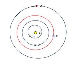
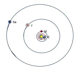
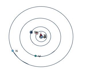
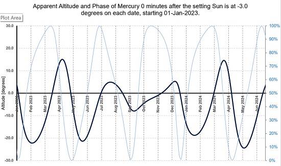
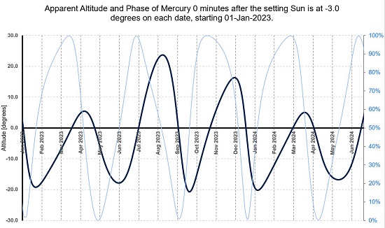
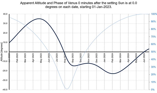
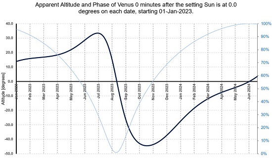
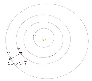 .......

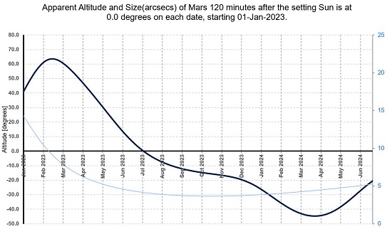
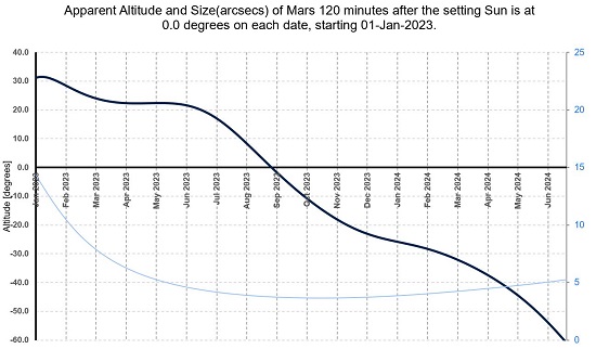
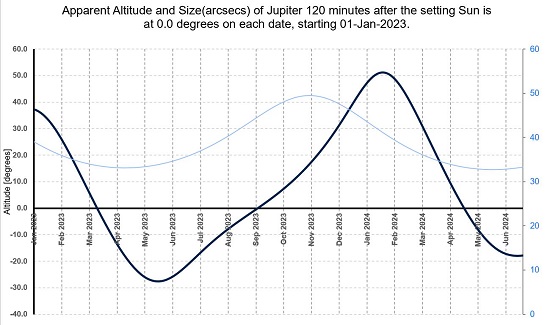
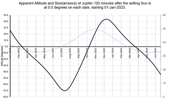
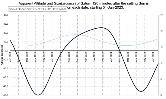
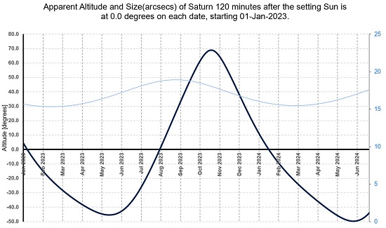
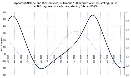
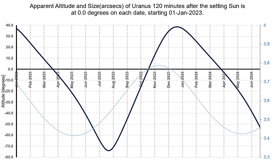
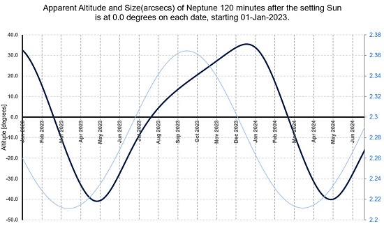
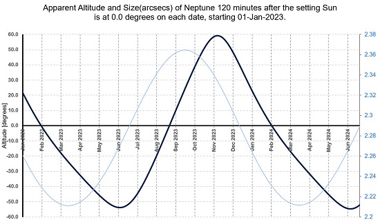
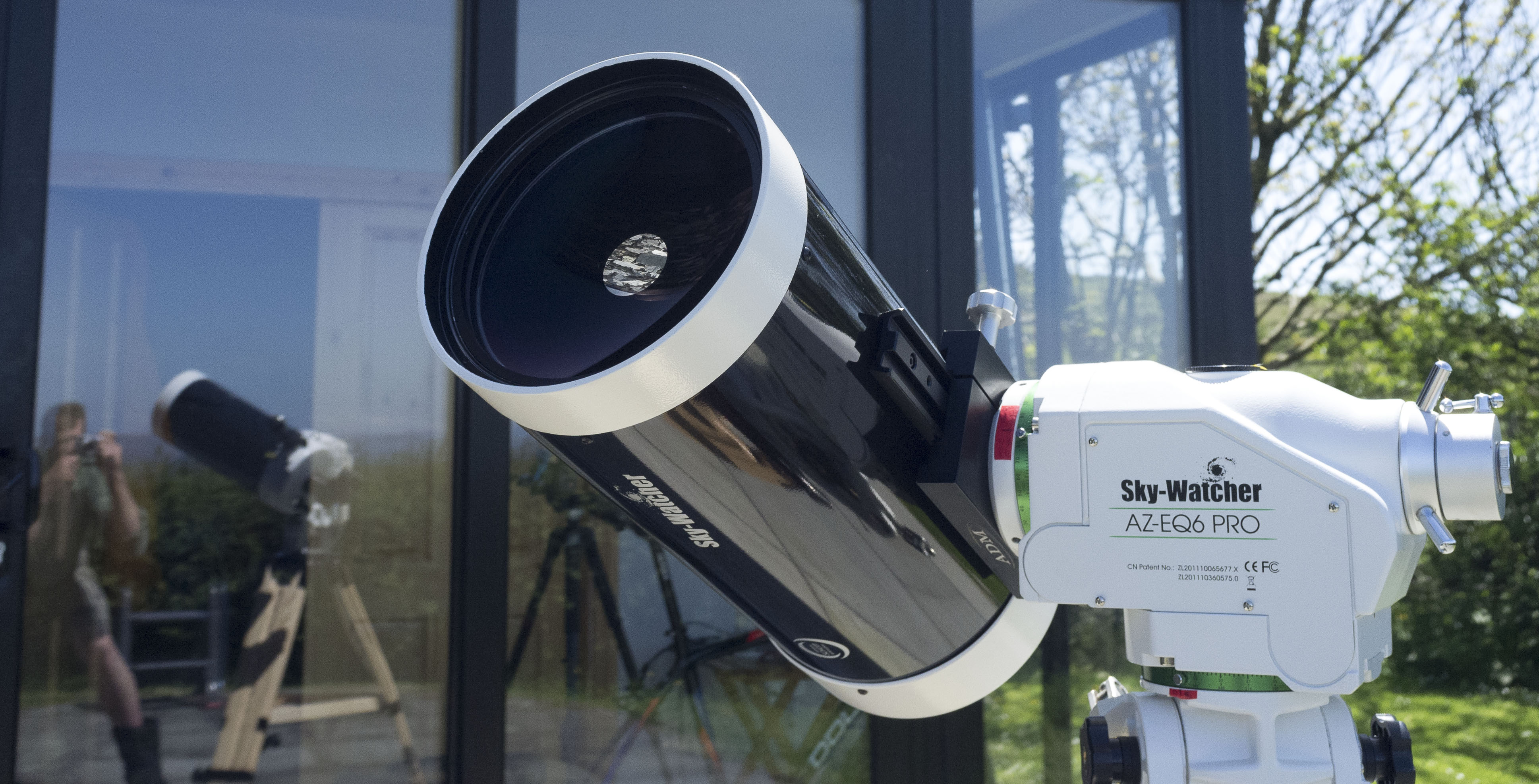
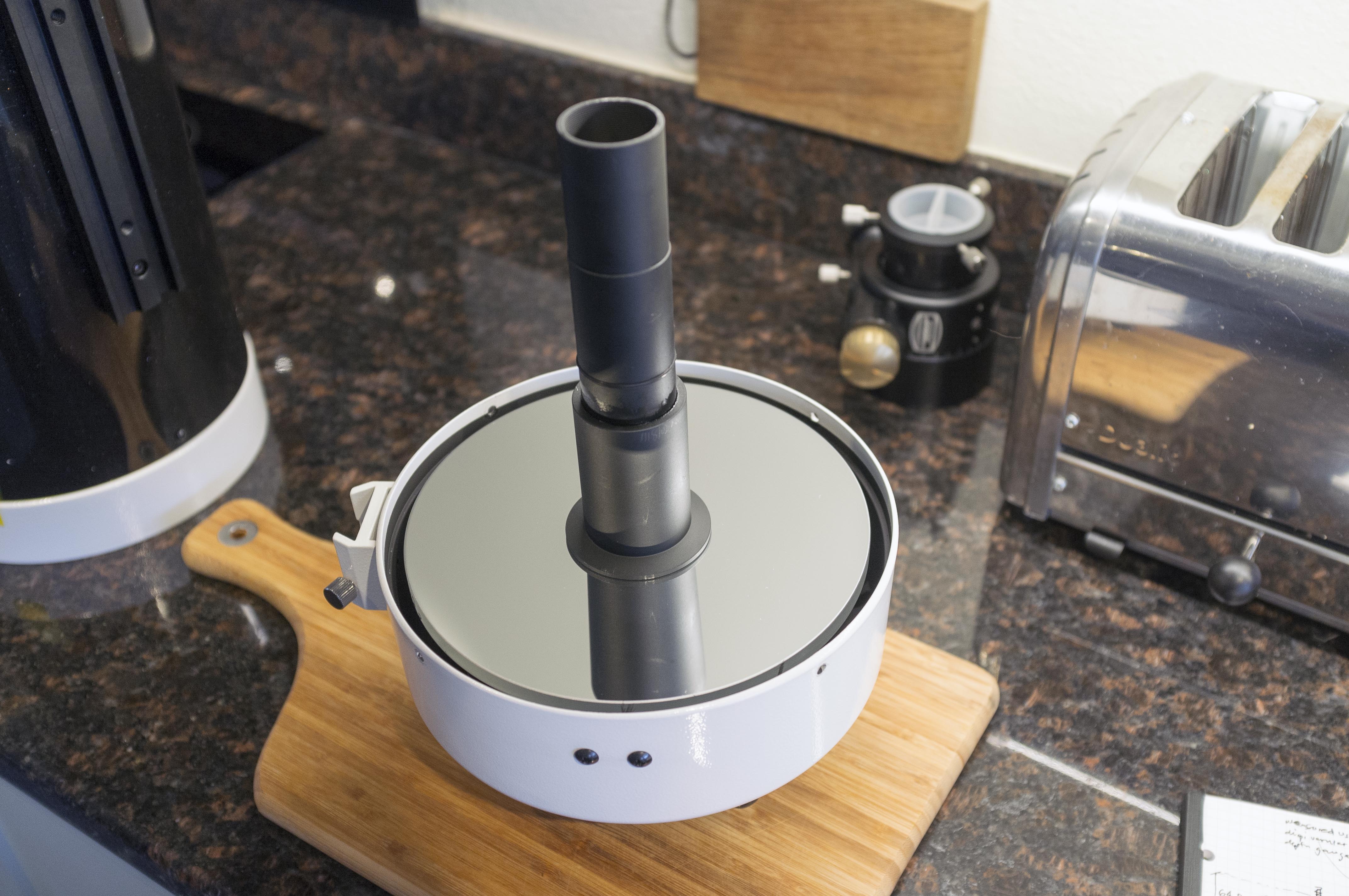


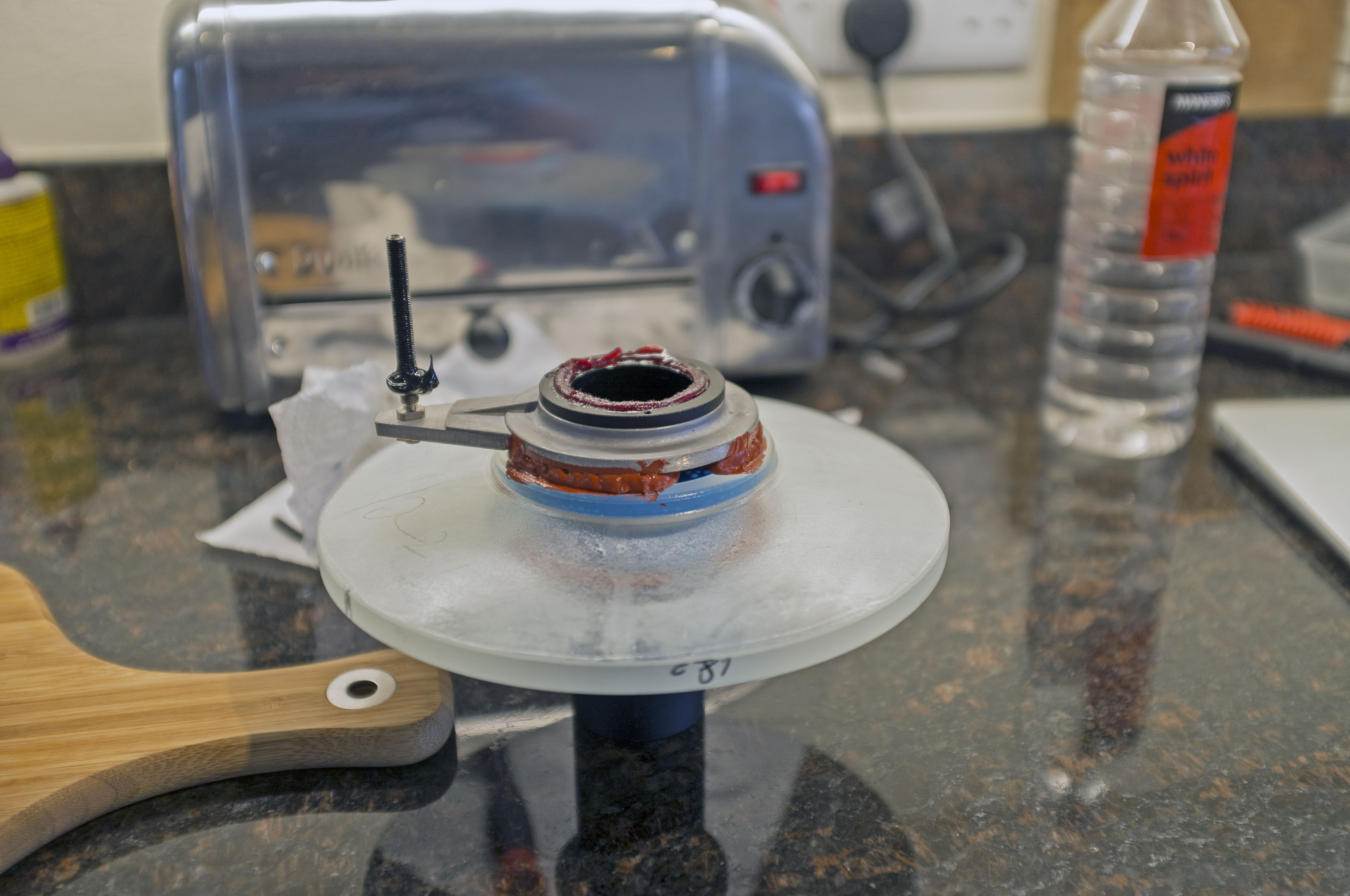

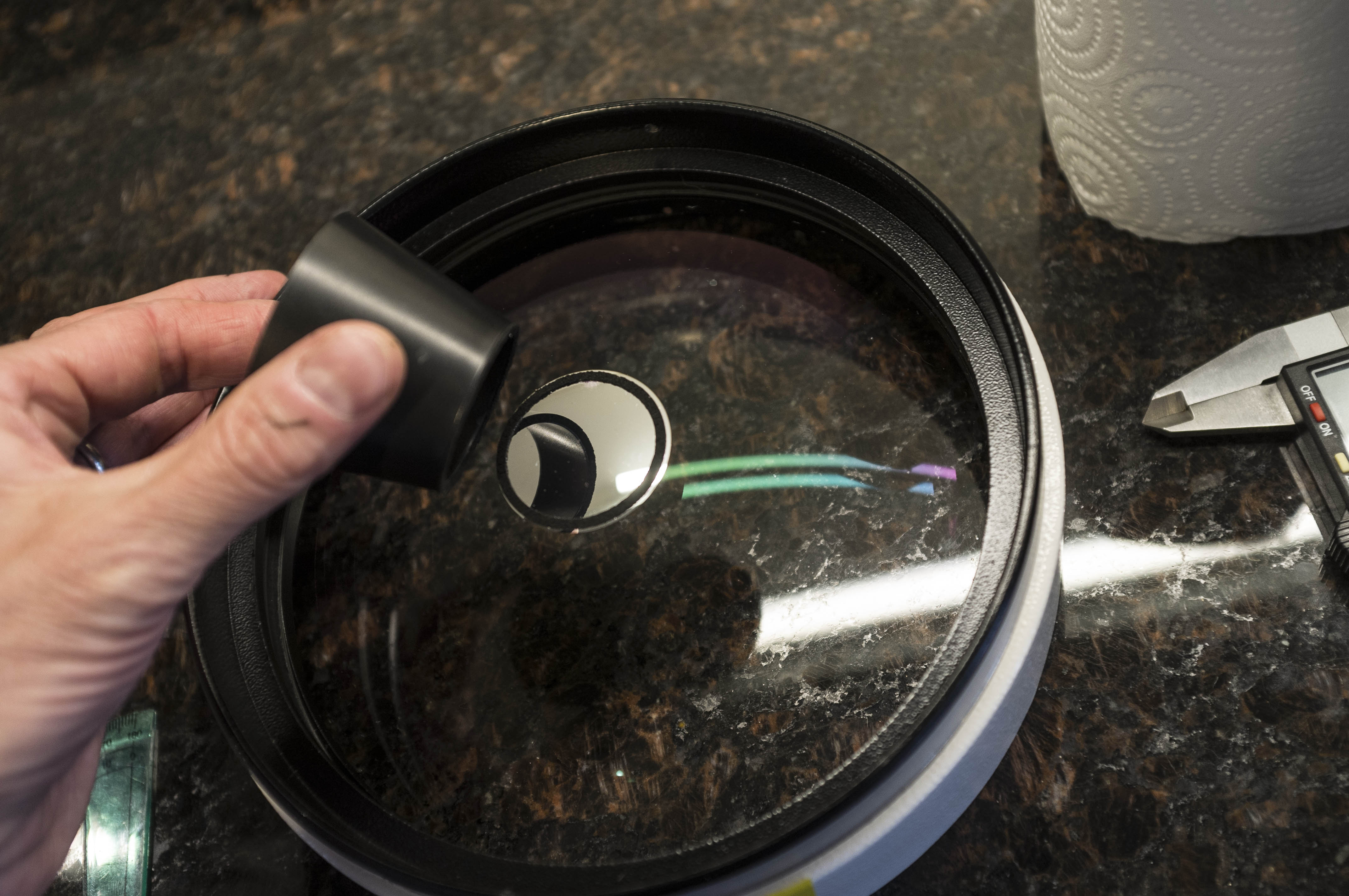
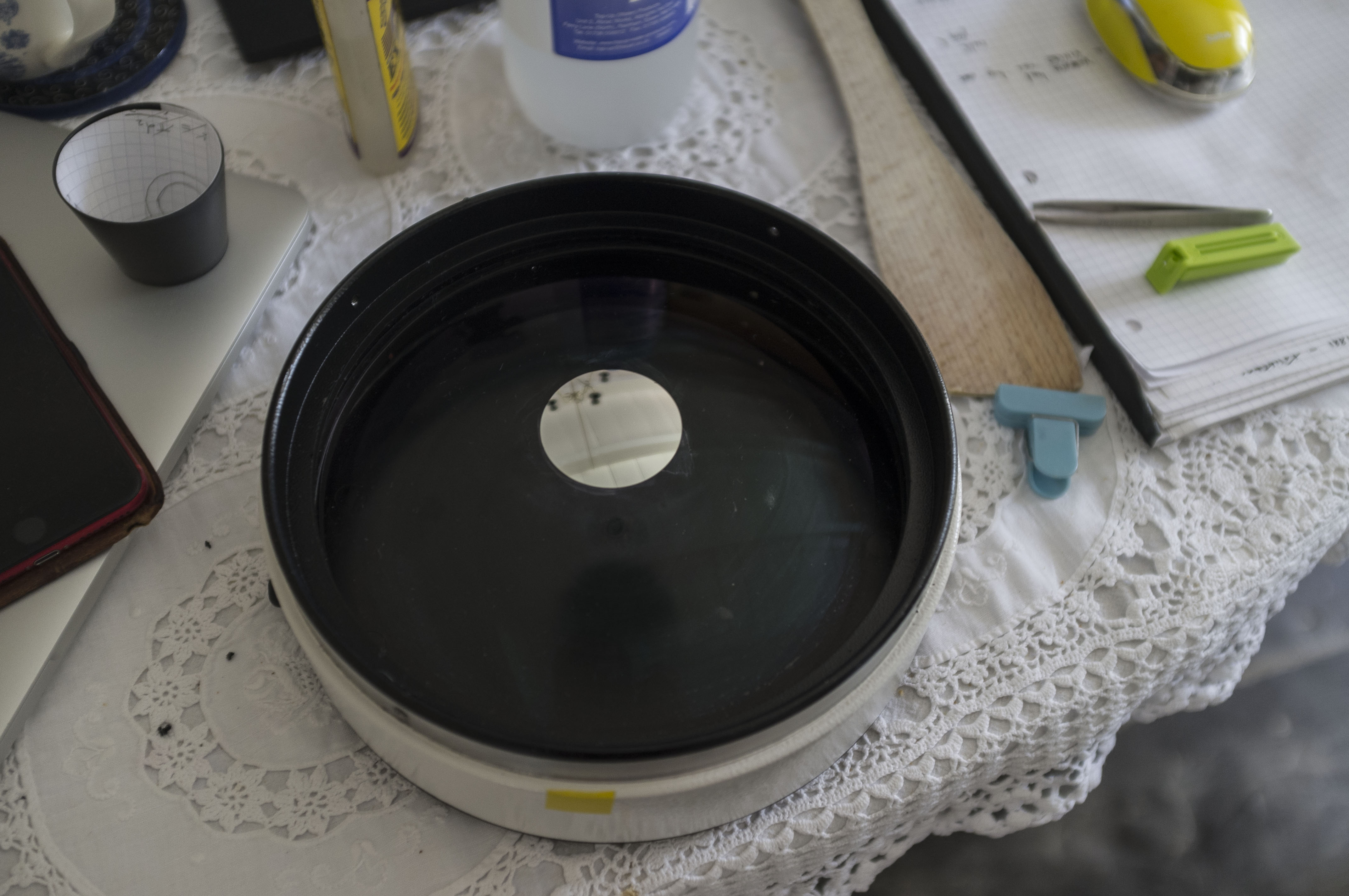

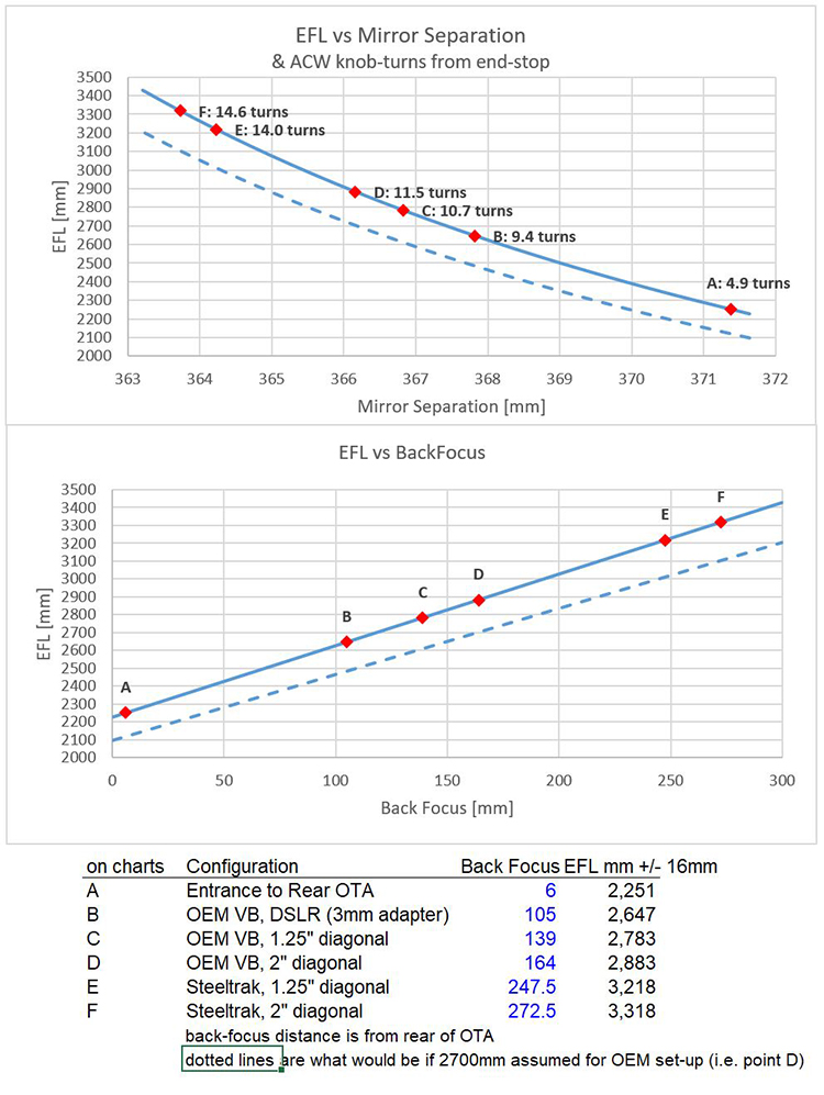

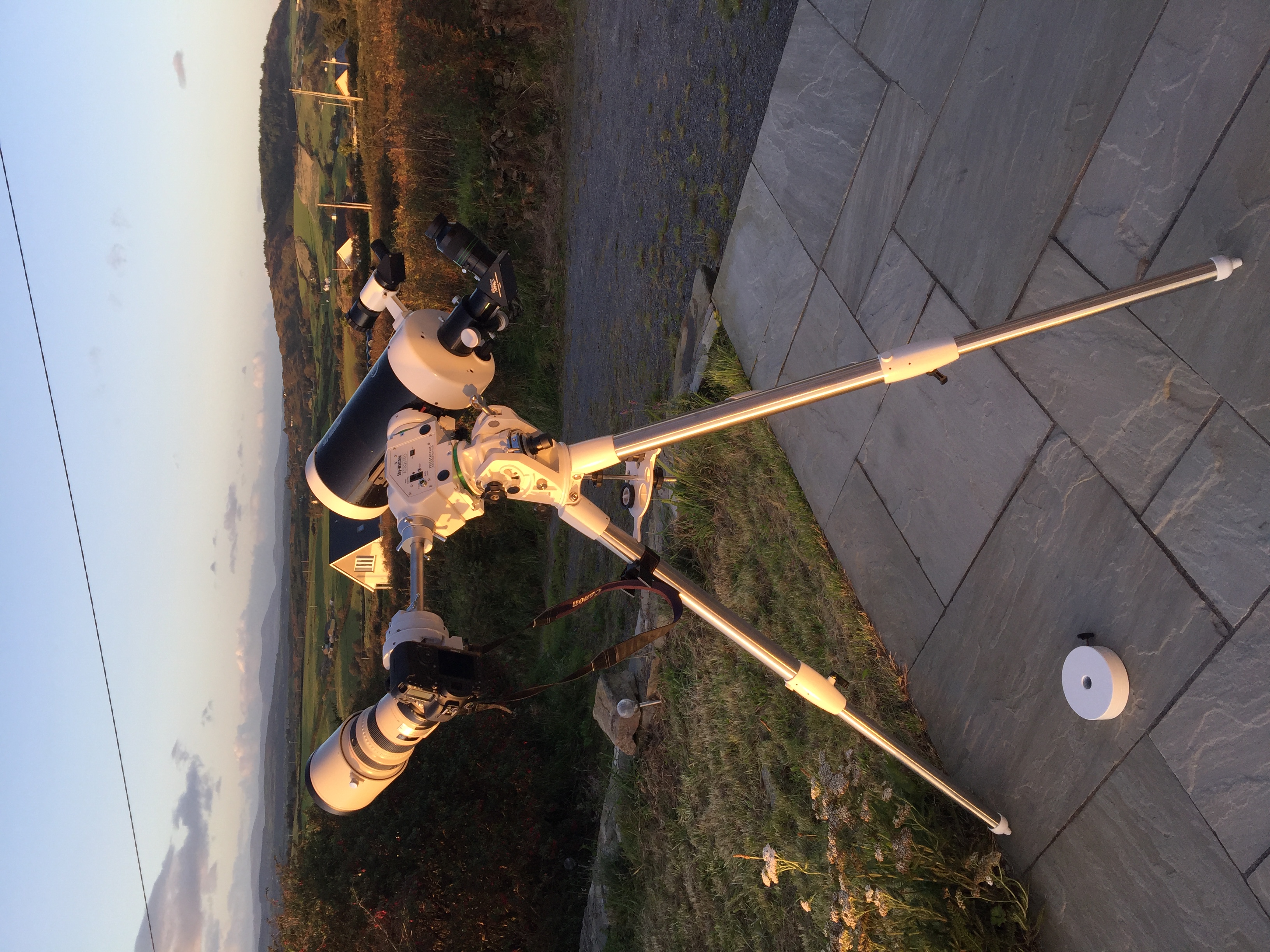
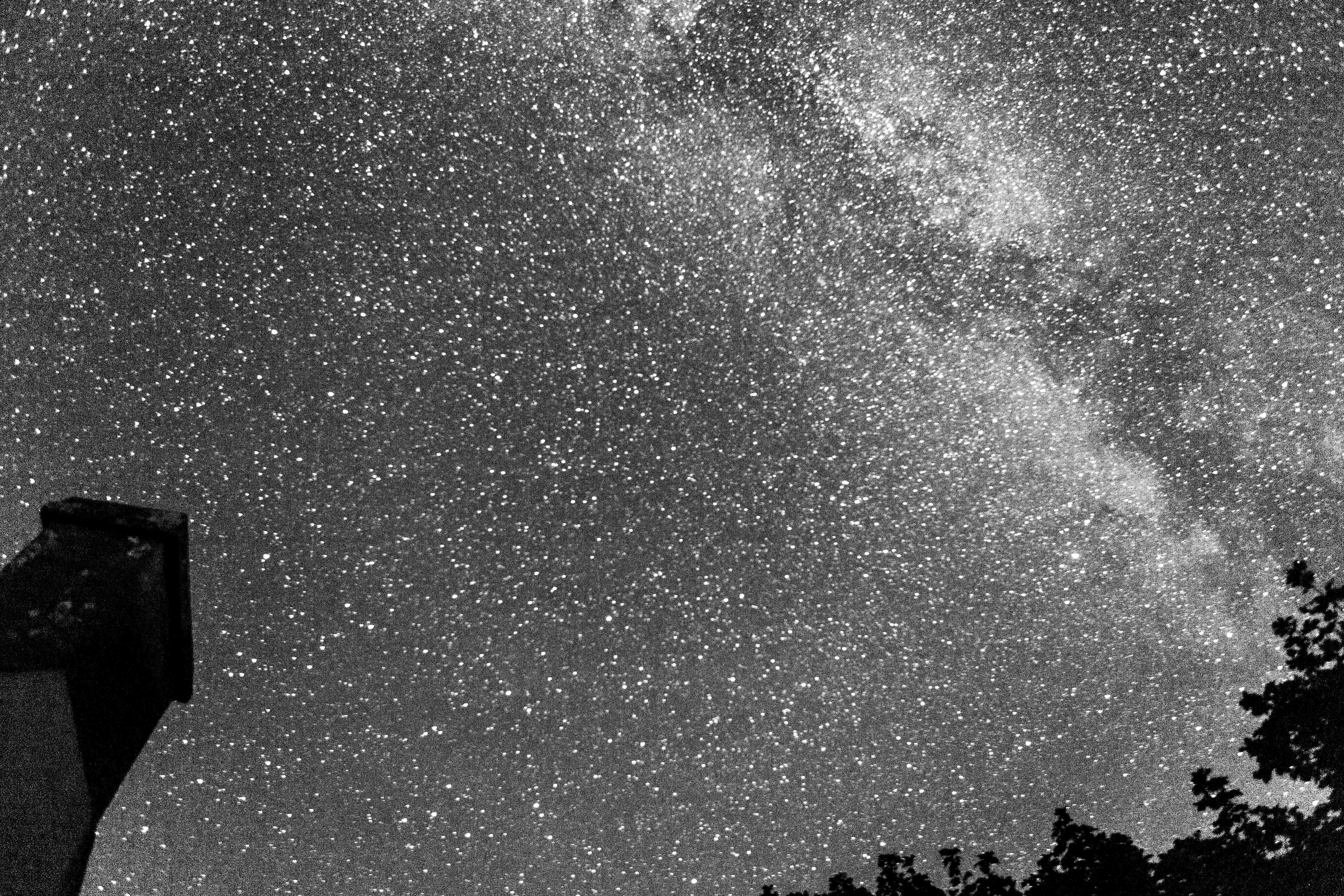
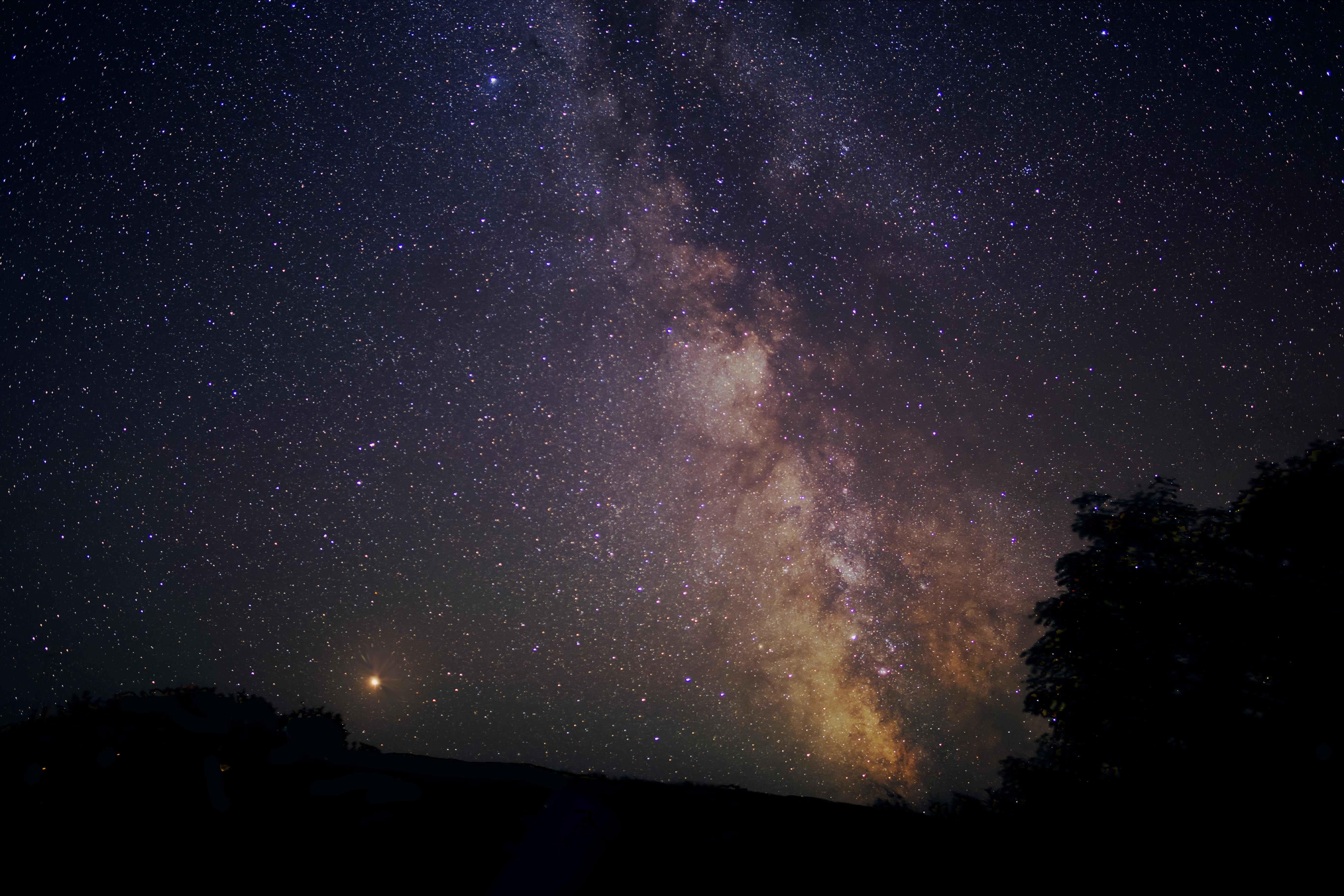
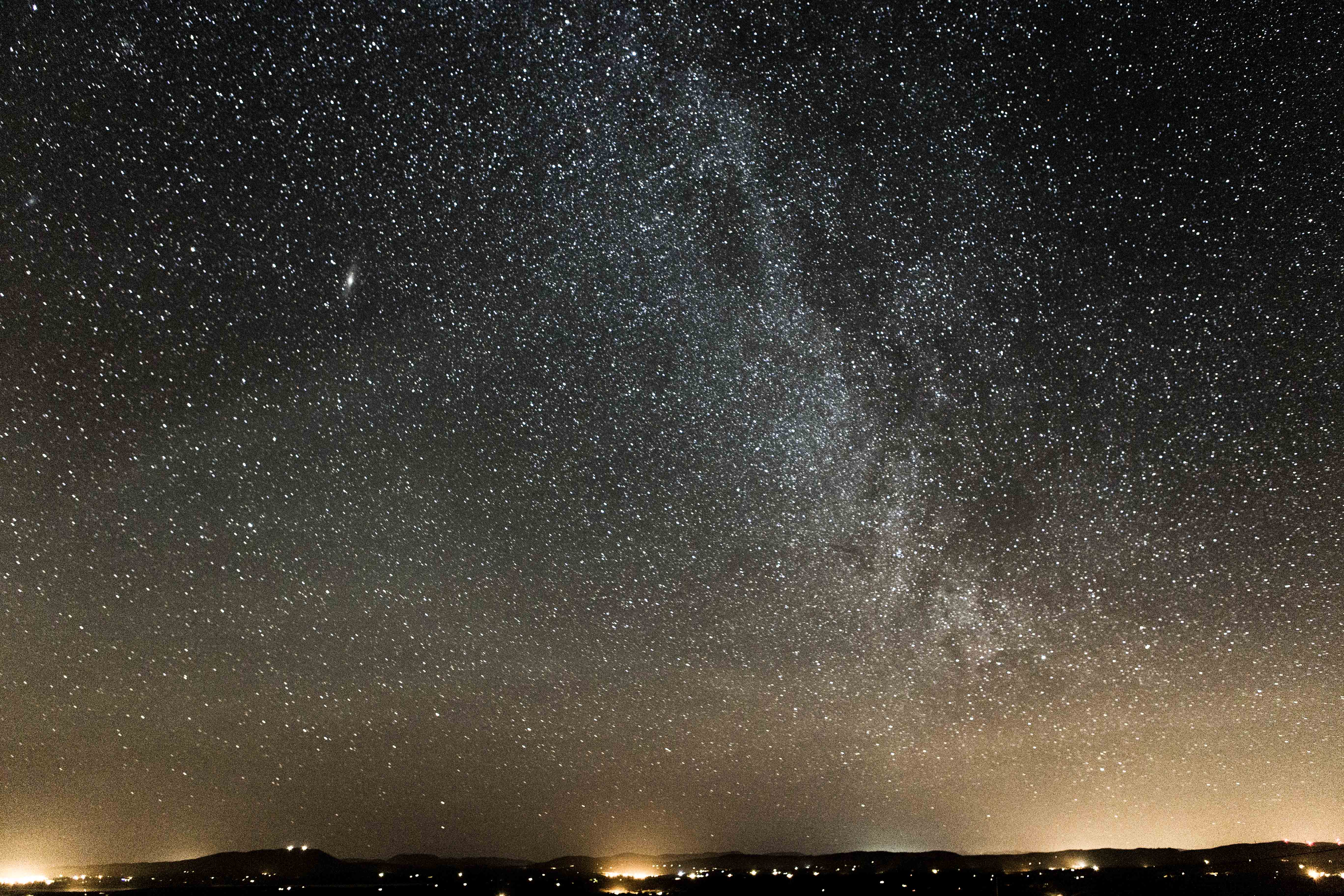
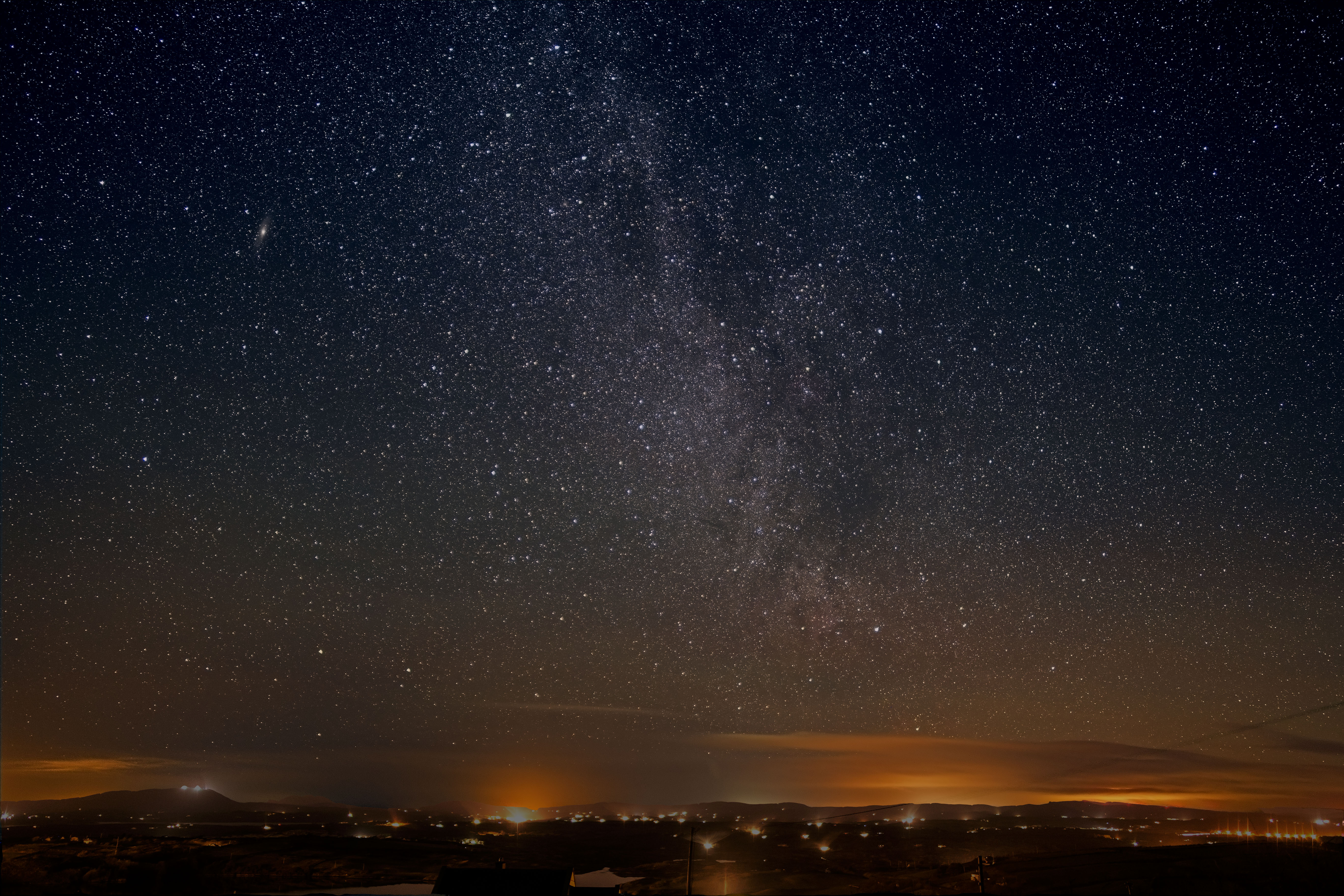
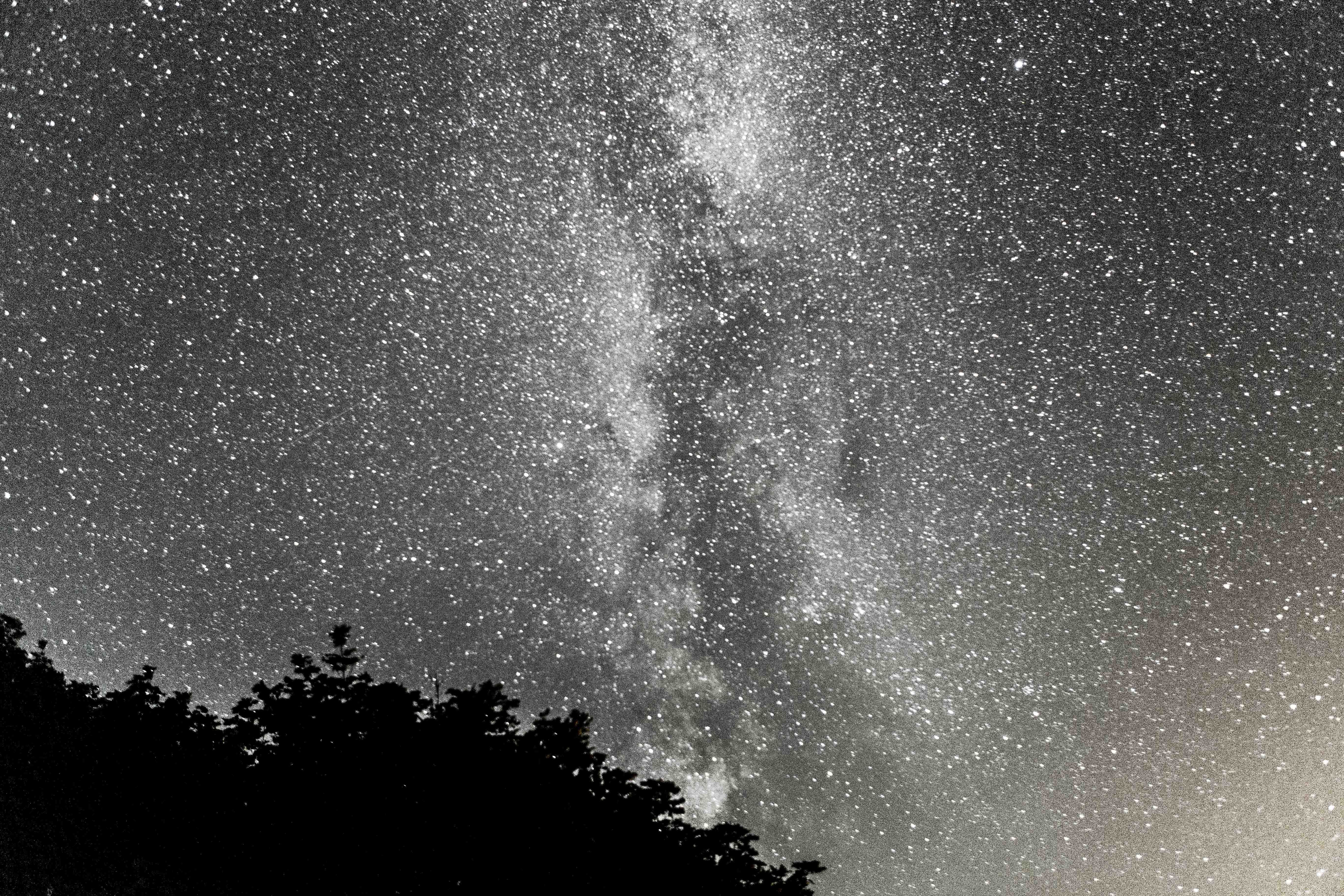
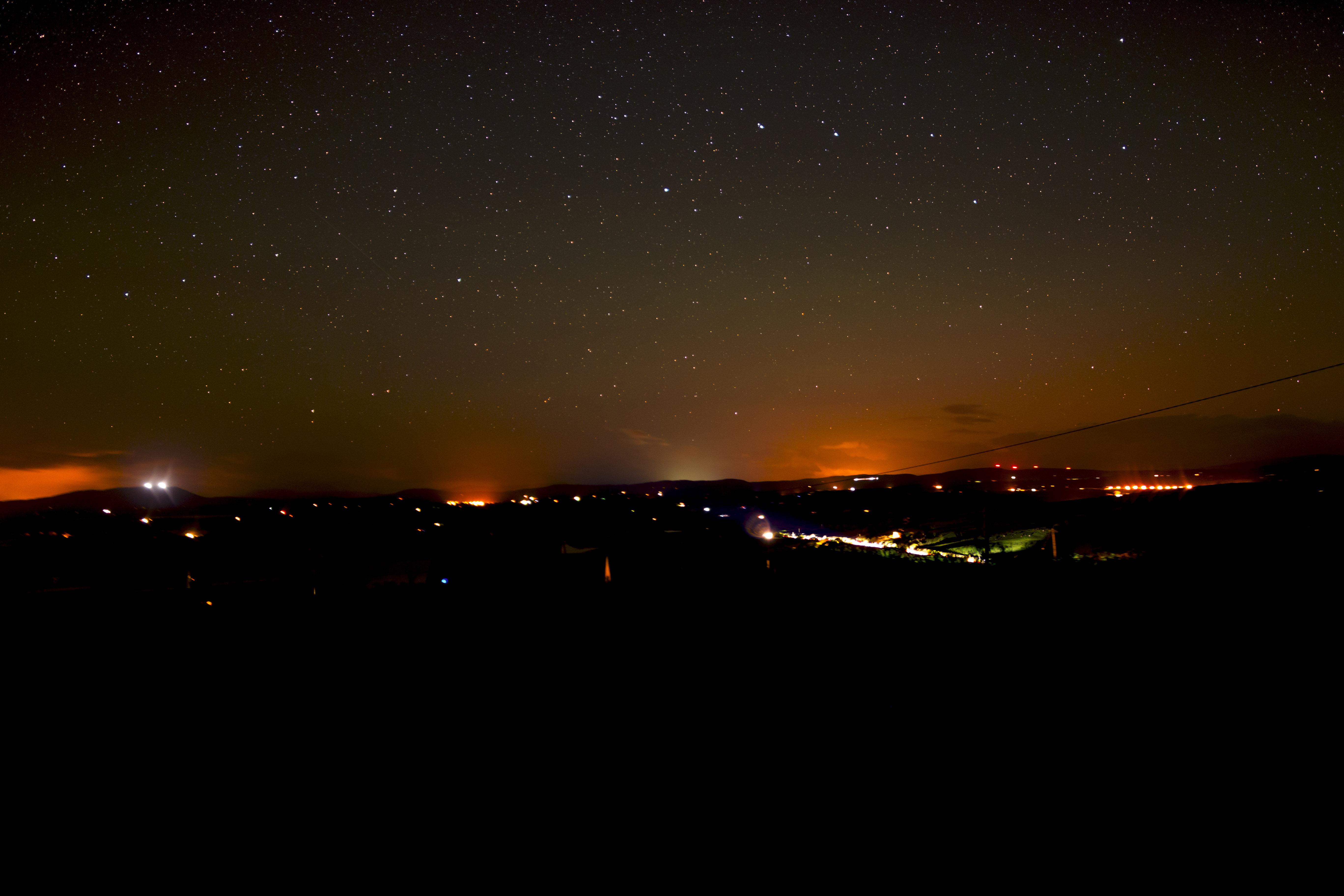
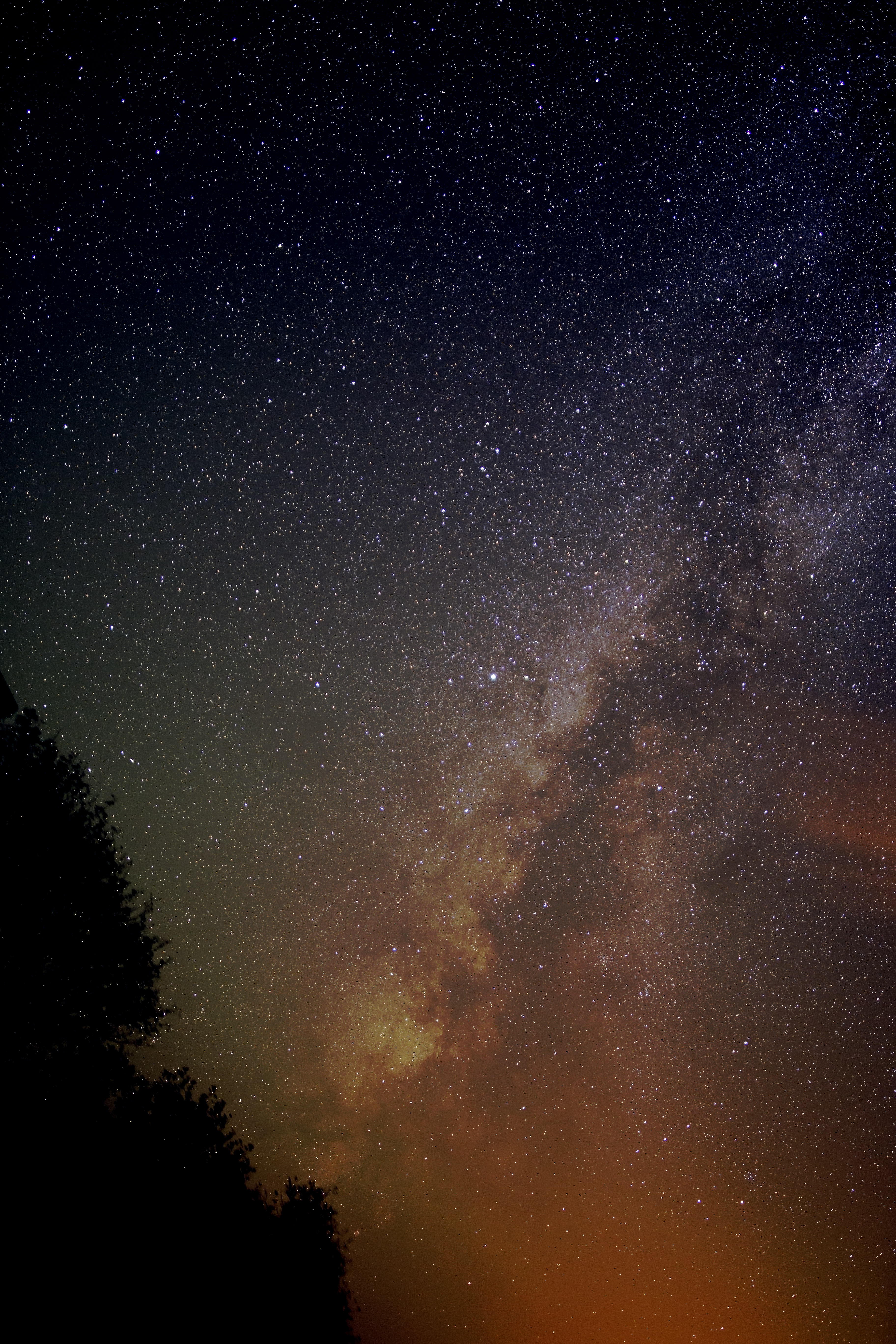
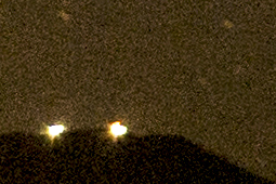 ............
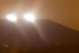

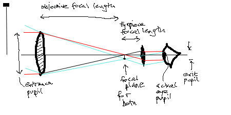
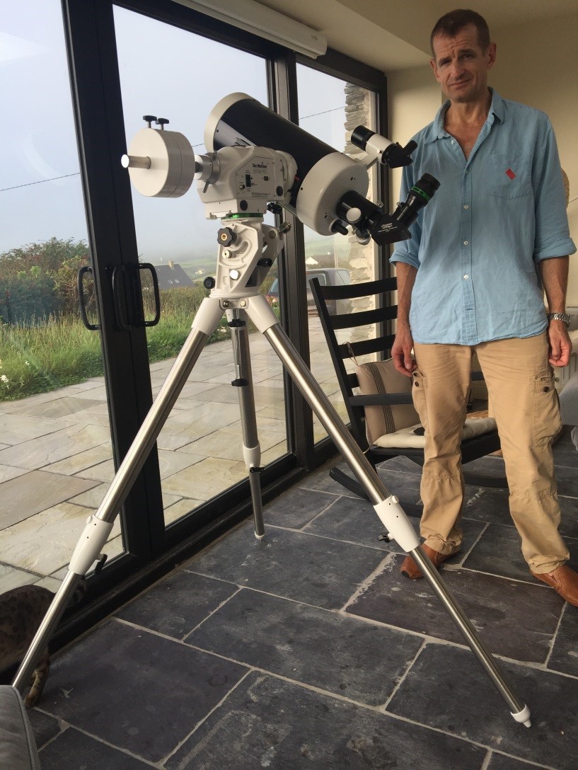

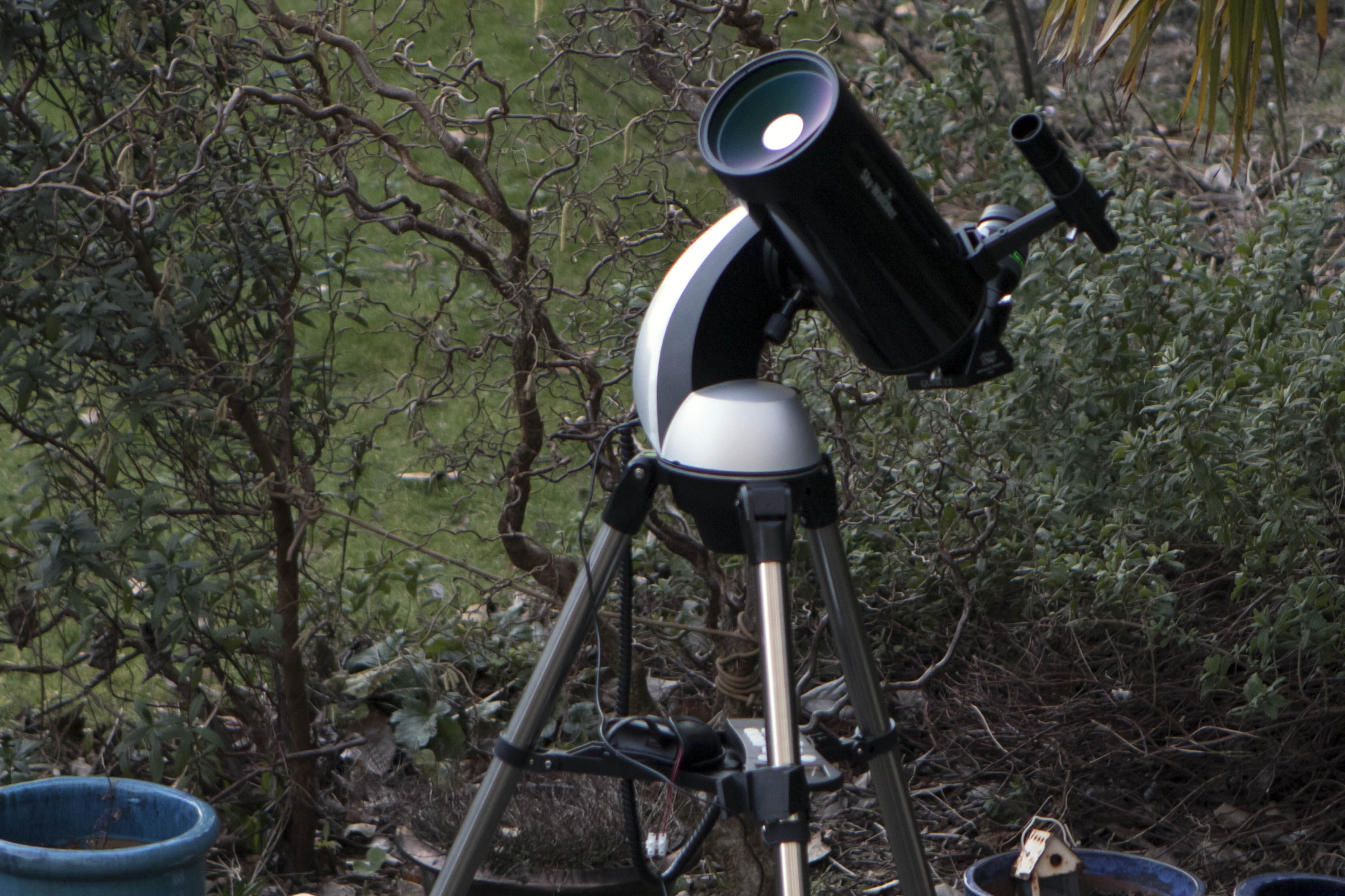
|
Each of the planets and when and how best to observe them for the coming year or two...
Ever wondered precisely how the Skymax 180, 150, 127 etc actually work, and what they look like inside? And what
actual focal lengths they're giving you?
My first attempt at photographing and processing a DSO (Deep Sky Object) with a DSLR...
An account of my first attempts to take decent nightscape and Milky Way pictures. Updated Jan 2021. My first ever astronomical telescope (and Mount): what, why, how, surprises, mistakes, lessons...
Number 2: After practising with my friend's SkyMax 127, I got one for myself...
|